Introduction
Bearing Pile Designer helps engineers to investigate the effects of soil parameters and different pile types and finally select a suitable pile type for known soil strata in accordance with both the Eurocode 7 and British Standard 8004:15, which provides detailed guidance on how to assess the capacity of piles in UK soils.
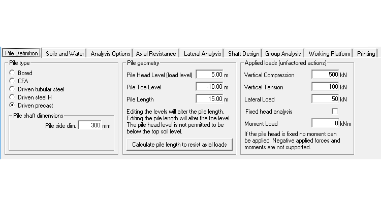
A simple to use program for checking the bearing capacity of individual piles and groups of piles of various lengths and types, including bored piles, continuous flight auger (CFA) piles, driven cast in place, driven tubular steel, driven steel H piles and driven precast piles.
A “Pile Length Calculator” can also be used to calculate the required length of pile for a given diameter/section size and required compression and tension capacity.
CADS Bearing Pile Designer can also assist with the thickness design of working platforms, piling mats, for tracked plant such as piling rigs, crawler cranes and mobile crane outriggers.
Summary
- Eurocode 2, 3 & 7 and British Standards 8004:2015
- Bearing pile capacity checks
- Individual and groups of piles
- Calculate pile length
- Various analysis options
- Working platform thickness design
- Specify soil layers and water table
- Soils generator based on standard borehole descriptions
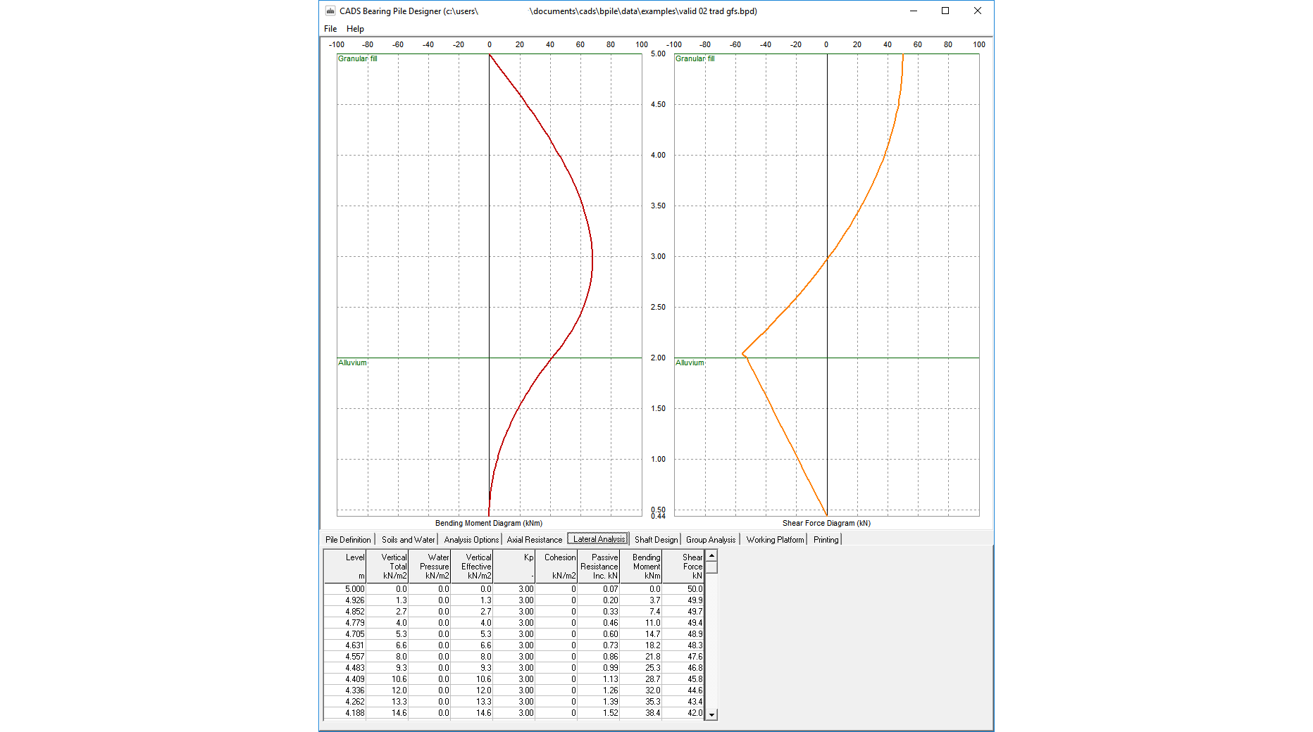
- Lateral load analysis included
- Graphical and tabular output
- Comprehensive printouts

"We have been using the CADS suite of software for over 20 years, the quality of the software and the level of support has always been outstanding"
Full description
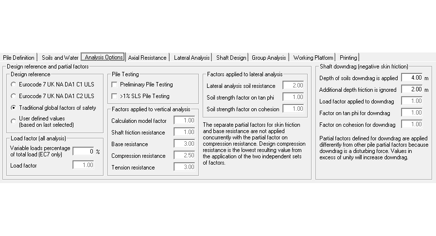
- The analysis options dialog showing the Factors of Safety tab.
- Carry out ultimate limit state type calculations.
- The theoretical unit shaft and end bearing resistances calculated using the program can be checked against maximum limit values specified in the Capacity Limits tab.
- The software automatically generates many of the necessary design coefficients from values given in standard texts.
- Skin Friction tab.
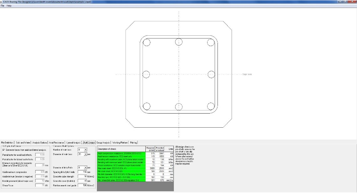
The pile forces obtained from the lateral load analysis (or an external source) can be used to design the shaft of the pile. Concrete piles are checked against Eurocode 2, Eurocode 7 and BS8004:2015. Steel piles are checked against Eurocode 3, Eurocode 7 and BS8004:2015. The results of the design checks are displayed in a simple summary which is colour coded to indicate pass or fail of each check.
Multiple soil layers and the water table can be input at defined levels, each soil layer can be specified as:
- Granular Phi – granular soils with shear strength based on Phi values (angle of internal friction)
- Granular SPT – granular soils with shear strength based on SPT values (standard penetration test)
- Undrained – cohesive soils with shear strength based on cohesion alone
- Drained – cohesive soils with both cohesion and phi values defined
- Chalk – special class with the strength defined by SPT values
The software includes a new module to check the thickness of working platforms for plant (including piling rigs, crawler cranes and mobile crane outriggers). This new module incorporates a range of analysis methods so that the user can assess the thickness required by each method and select an appropriate thickness of mat to provide.
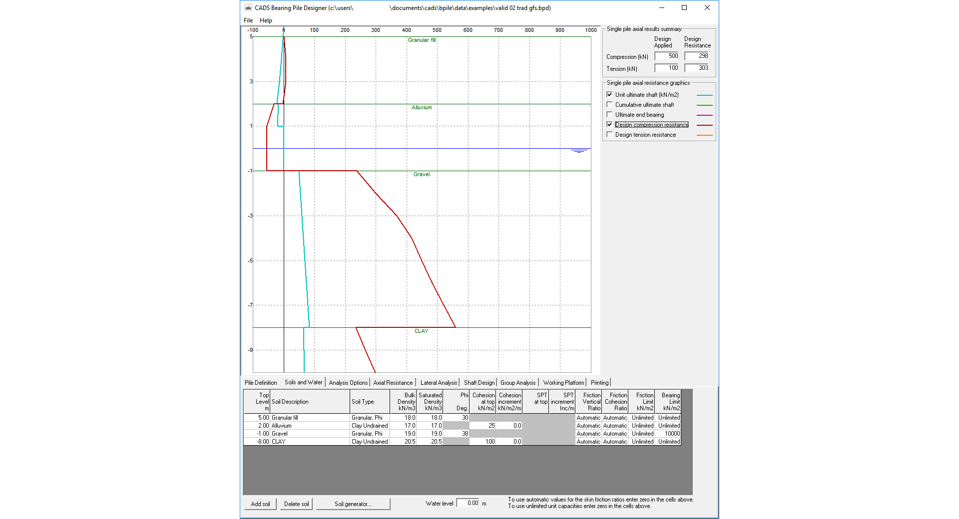
The graphical output displays the variation of pile capacities with depth for ultimate shaft resistance, end bearing resistance and design compression/tension resistance.
Results can also be viewed in a table which details values at 0.25m intervals unless otherwise specified by the user. These values include vertical overburden and water pressure, the effective vertical stress, the internal friction angle (Phi), cohesion, SPT and pile capacity values.
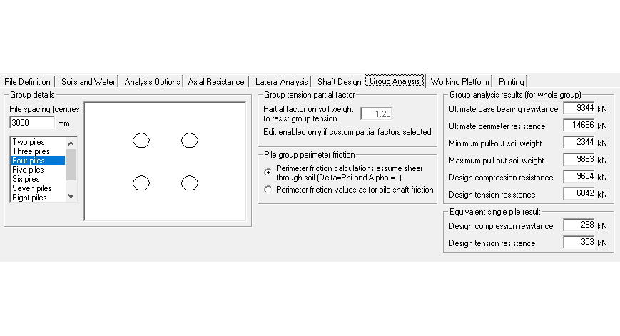
Pile groups of 2 to 9 piles plus an “infinite” option can be prescribed along with the minimum pile spacing to calculate the overall group capacity. The load resistance calculation of the group follows similar calculation methods to those used for single pile analysis. An additional check for soil weight resistance is included. The perimeter and base areas of groups of known size are easily determined from basic geometry. For infinite groups, the group checks are carried out on an individual pile within the infinite group. In the ultimate values, negative skin friction is included as well as soil strength factors. Numerical results provided include the ultimate bearing and compression resistance, design tension capacity as well as a set of values for an equivalent single pile.
Related software