
Introduction
Steelwork Member Designer is a program which prepares calculations for the strength, stability and stiffness of steel members to the requirements of EC3 and BS 5950 Part 1 2000.
Engineers specify what they consider to be a suitable section for the software to check or run the ‘Automatic Design’ mode to see a list of suitable section types that meet the BS 5950 requirements under the specified loading conditions. This application may be used entirely stand-alone to design individual steel members or used in conjunction with CADS A3D MAX frame analysis software to design an entire building frame.
Summary
- ‘Stand-alone’ or linked to frame analysis
- Links to CADS design and detailing software
- International steel section library
- Tapered and haunched members
- Independent design capability
- Automatic design feature
- Comprehensive ‘on-screen’ results
- BS 5950 support
- EC3 support
- Links to CADS A3D MAX
Try Steelwork Member Designer
Video demos
Download a brochure

"We have been using the CADS suite of software for over 20 years, the quality of the software and the level of support has always been outstanding"
Full description
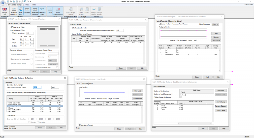
When running CADS SWMD stand-alone the user first selects a section from the internal section library or runs the ‘Auto-Design’ to see a selection of suitable sections for the specified conditions.
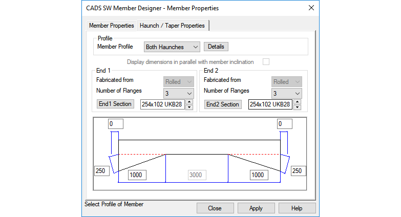
If CADS SWMD is run in conjunction with frame analysis software, then the section properties are imported automatically. The program allows for all permutations of tapered members and those with two, three or four flange haunches. The section properties for positions in the non-uniform parts of haunched and tapered members are calculated by the program during its execution.
A group of holes may be specified and applied to all or part of the member length and an allowance is made for the local increase in design strength available at holed sections due to strain hardening.
The support conditions are defined, and lateral restraints may be applied at the ends of the member and at intermediate positions along its length to prevent buckling. Options include point restraints (supported beam, purlin or bracing) or distributed/continuous restraint (concrete floor slab, sheeting or decking) and are easily defined via an easy to use Windows dialog box.
Restraints applied to a single flange may be offset by a specified distance, to take account of, for example, purlin cleats.
CADS SWMD divides steel members into potential lateral buckling lengths and provides default values for the effective length factors based upon an interpretation of tables 9 and 10. However, these values may be marked as being subject to de-stabilising loads or edited by the user to accommodate any special conditions or interpretations. As well as EC3, members can be checked for lateral buckling according to BS 5950 section 4, and for torsional buckling to Appendix G of BS 5950 Part 1.
Designers using CADS SWMD in `stand-alone´ mode may create several combinations of uniform, distributed, point and/or moment load types and the software will perform its own analysis to calculate their effects. For ease of use some or all of the loads may be configured to appear on the main screen display.
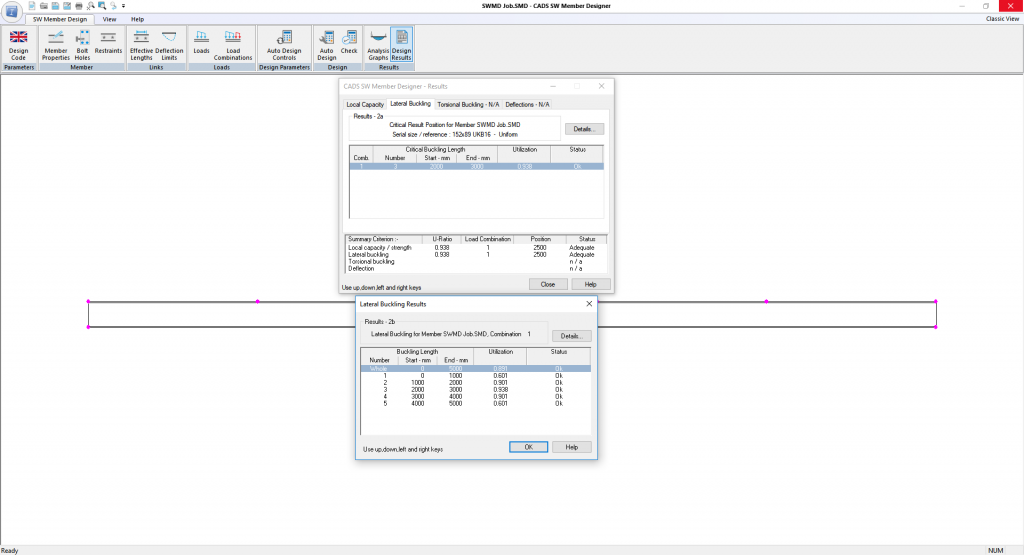
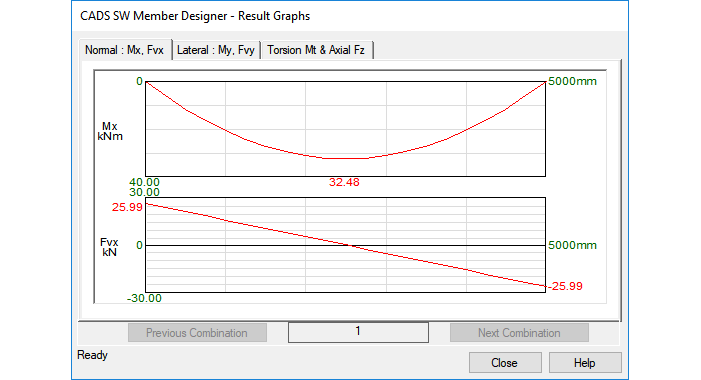
Once the calculations have been completed the results summary reports the most critical `utilisation factor´ for local strength capacity, lateral buckling, torsional buckling and deflection. For more detailed results, full calculation results are easily displayed. Alternatively, the graphical results option displays a diagram of the member showing the support conditions and restraints in plan and elevation with diagrams of axial, shear and moment effects. Designs can be refined quickly by simply selecting an alternative section type, size or changing the lateral restraints and/or details of the haunch.
Once the design has been fully completed, CADS SWMD provides a comprehensive, user definable ‘calculation style’ printout suitable for inclusion with other calculations for project QA documentation and submission for Building Regulations check.
Related software