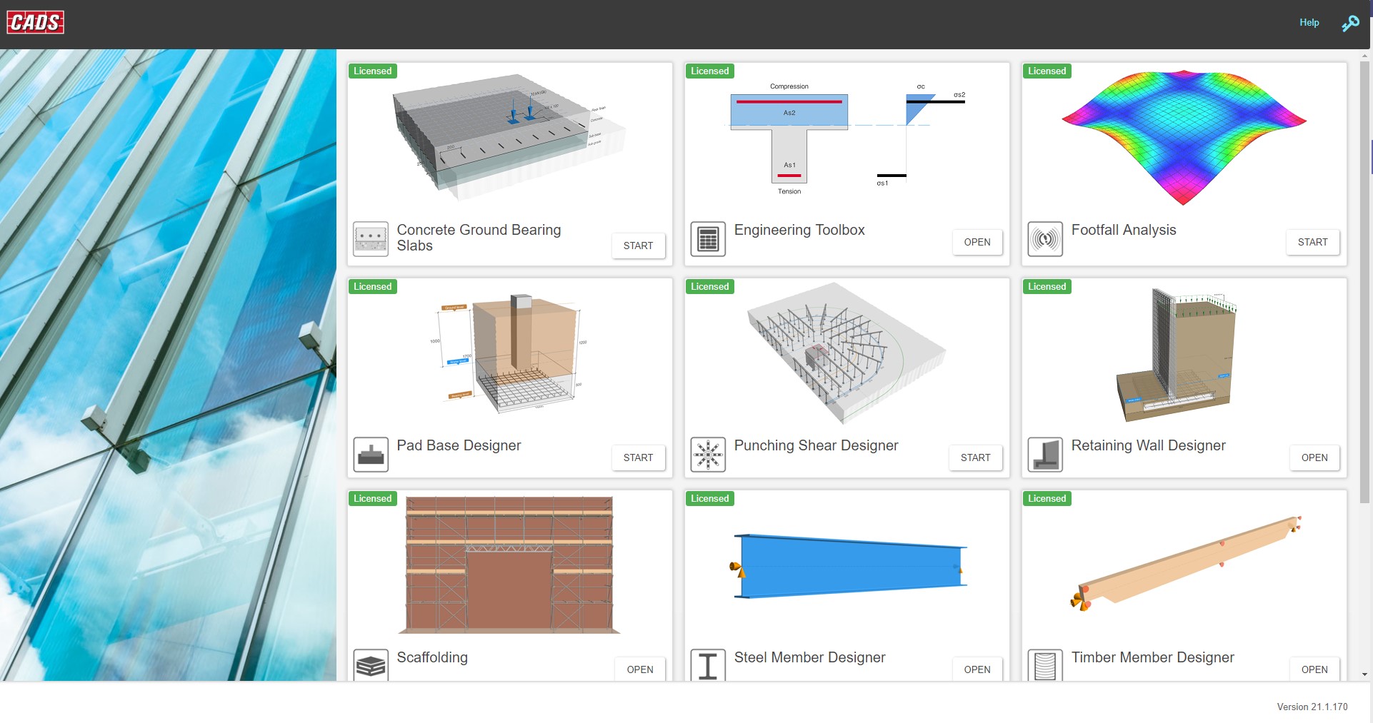
CADS Hub – Design Applications
All applications in one place!
Features and Benefits At-A-Glance
See below the list of applications found within CADS Hub. A free trial will contain a restricted version of all the apps and you only purchase the ones you need.
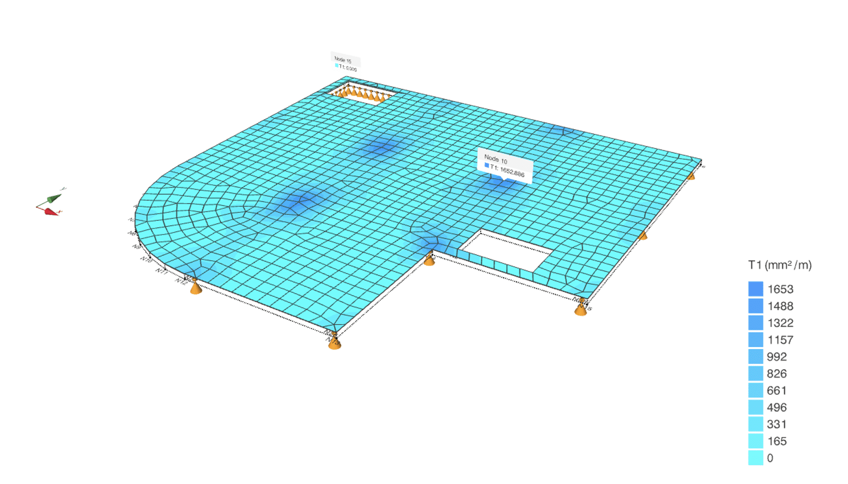
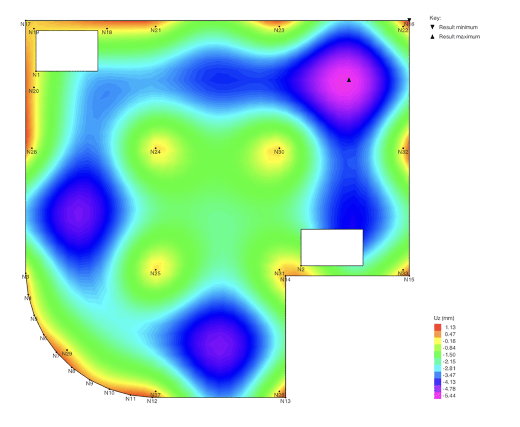
RC Slab Designer is a software application that can perform structural analysis and design of slab panels. The Finite Element (FE) analysis is carried out using the NASTRAN solver and the design calculations are carried out in accordance with EN 1992-1-1.
The application performs calculations for flexure, shear and crack width. The reinforcement required, provided and the excess/deficit is displayed over the slab surface graphically.
All the analysis and design results can be exported to PDF and MS Excel format. The design steel can also be exported to CADS Smart Slab Detailer/CADS RC where the reinforcement can be further detailed.
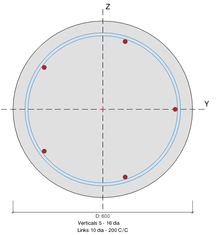
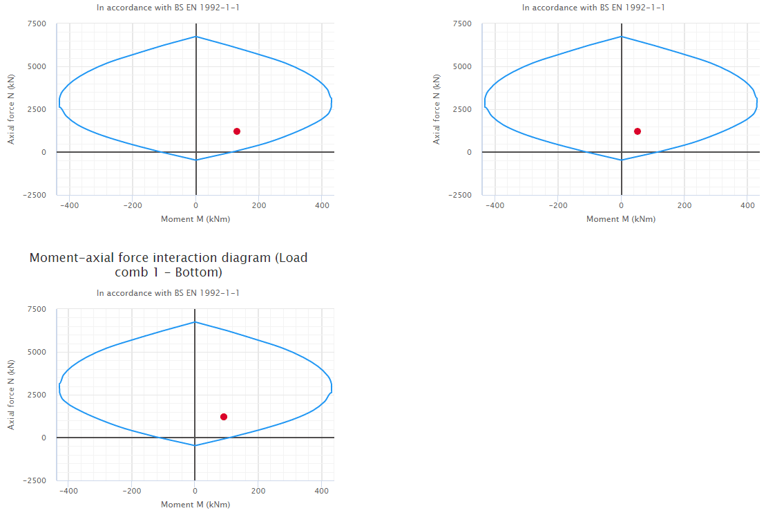
CADS RC Column Designer is a program intended to assist in the structural designing of a reinforced concrete column based on the Eurocode guidance BS EN 1992-1-1:2004, in accordance with the UK National Annex. The program provides an analytical and design tool to calculate and check the structural capacity of the column.
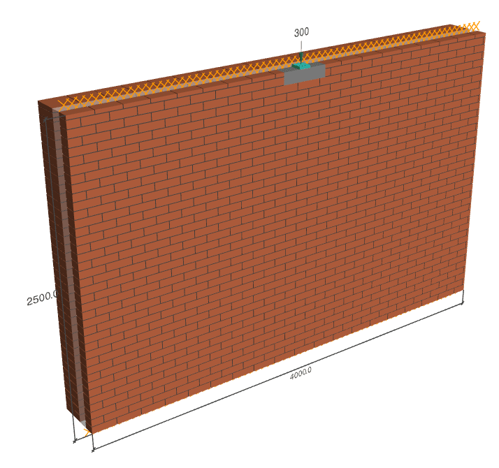
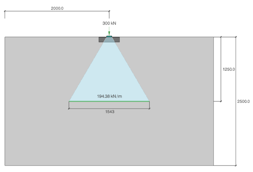
CADS Masonry Bearing Designer is a software application for assessing the vertical load-bearing capacity of masonry wall panels subjected to point loads and uniformly distributed loads. The application supports both single-leaf and cavity wall configurations, with options for plain walls or walls with piers. Design checks are carried out in accordance with BS EN 1996-1-1:2005+A1:2012 and UK National Annex.
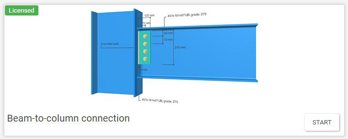
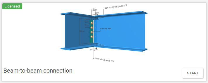
CADS Steel Simple Connection Designer is a program for checking of simple connections based on BS EN 1993:2005 – Design of Steel structures – Part 1-8 Design of joints and SCI P358 – Joints in steel construction: Simple joints to Eurocode 3.
The following types of connections can be checked by this application:
- Beam-to-beam connection (end plate or fin plate)
- Beam-to-column connection (end plate or fin plate)
- Column splice (bearing or non-bearing)
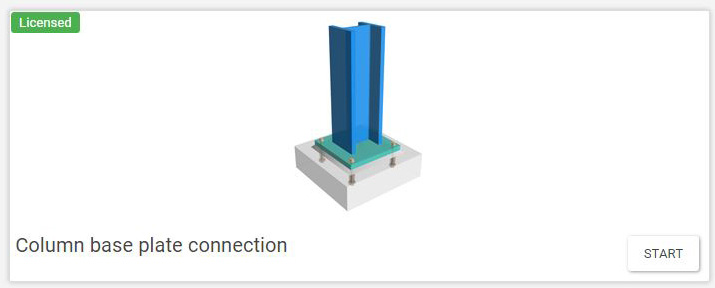
- Column base plate
- Beam-to-beam splice
According to BS EN 1993-1-8:2005 nominally pinned joints, checks of the joint are made to ensure it;
- Should be capable of transmitting the internal forces, without developing significant moments which might adversely affect the members or the structure as a whole;
- Should be capable of accepting the resulting rotations under the design loads.
- Can provide the directional restraint to members which has been assumed in the member design;
- Will have sufficient robustness to satisfy the structural integrity requirements (tying resistance).
Verification checks, below, are also made of the strength of a nominally pinned joint;
- To ensure that the joint is detailed such that it develops only nominal moments which do not adversely affect the members or the joint itself. The joint should be detailed so that it behaves in a ductile manner;
- To identifying the load path through the joint i.e. from the beam to the supporting member;
- To check the resistance of each component.
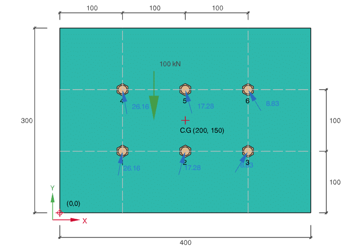
Bolt Group Analysis
CADS Bolt Group Analysis is a software application to calculate the forces in a bolted connection. The program uses the elastic method to calculate and check the force distribution in a connection subjected to vertical, horizontal, inclined, and torsional loading.

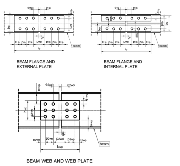
Beam-to-beam splice connection
In beam-to-beam splice connection the forces are transferred through the cover plates and bolts. The web splice plates and bolts are typically responsible for transferring vertical shear forces between connected beam segments. The flange plates and associated bolts transfer the tension and compression resulting from the bending moment at the splice location, like the flanges in the main beam.
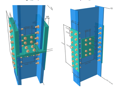
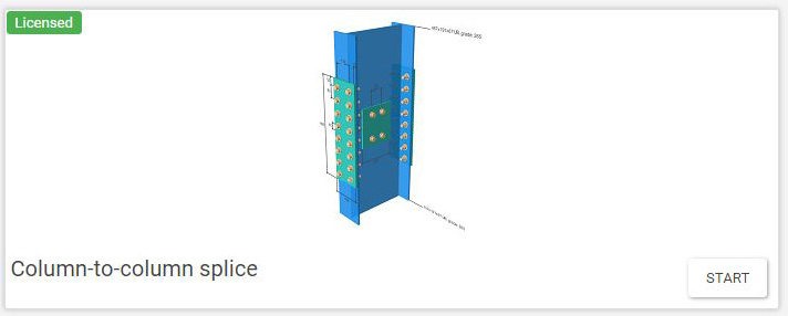
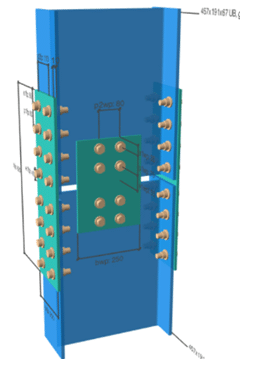
Column-to-column splice connection
There are two types of column splice connection:
Top image: Bearing type (with or without division plate);
Bottom image: Non-bearing type.
CADS Steel Member Designer is a program for checking and designing structural elements as per BS EN 1993-1-1:2005+A1:2014 – Design of Steel structures – Part 1-1 General rules and rules for buildings for UK and Irish National Annexes.
The current version of the software contains three modules for the design of:
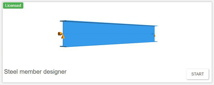
Steel Member Designer
For the design of Beams (single and multi-span, inclined or horizontal) and Columns.
Design is based on BS EN 1993-1-1:2005+A1:2014 – Design of Steel structures – Part 1-1 General rules and rules for buildings for UK and Irish National Annexes.
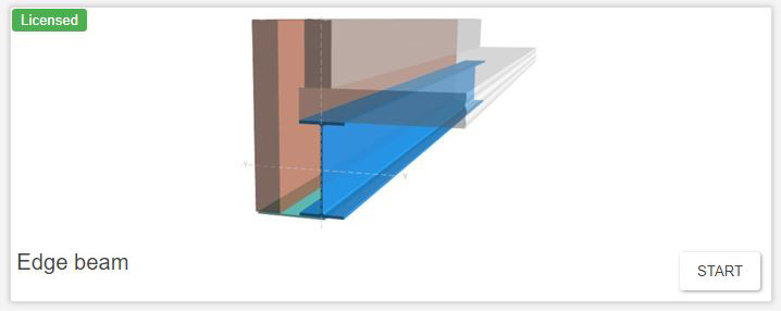
Edge Beam
CADS Edge Beam is a program for verification of a single-span steel edge beam under eccentric wall loading based on BS EN 1993-1-1:2005+A1:2014 – Design of Steel structures – Part 1-1 General rules and rules for buildings and Steel Construction Institute P 364 – Steel building design – worked examples – open sections. The calculations are based on the simplified method permitted by clause 6.2.7(7) of the aforementioned Eurocode.
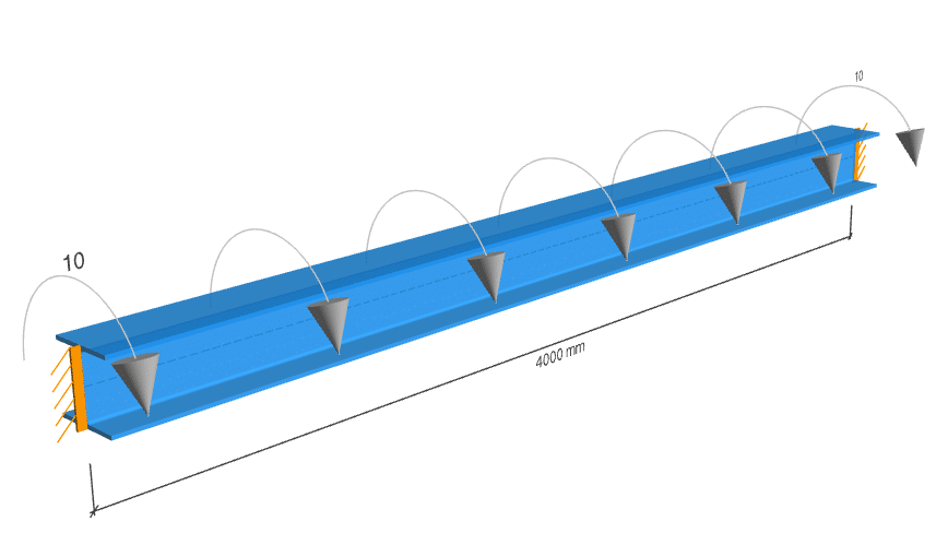
Steel Beam Torsion Check
CADS Steel Beam Torsion is a software application for verifying the strength and stability of steel beam sections subjected to torsional loading. The calculation also takes into account combined actions, including bending moments about both major and minor axes, shear forces along with the torsional loading. Design checks are carried out in accordance with EN 1993-1-1, EN 1993-6, the UK National Annex to EN 1993 and the Ireland National Annex to EN 1993, and guidance from SCI P385.
The beams are assumed to be single-span, simply supported members, with cross-sections that include rolled I and H-sections, asymmetric I-sections, channel sections, and both rectangular and circular hollow sections.
The application considers both uniform torsion and warping torsion in the calculation.
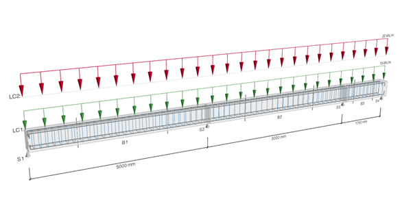
CADS Reinforced Concrete Beam Designer is a software application for the design and verification of reinforced concrete (RC) beam members in accordance with BS EN 1992-1-1:2004 + A1:2014 and the UK National Annex. The application supports both design and check modes, allowing users to either determine the required reinforcement or verify adequacy of the provided reinforcement.
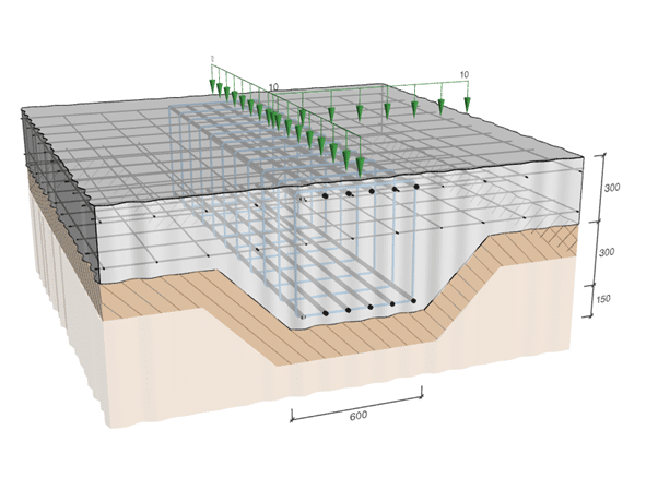
CADS Raft Foundation Designer application performs spot design checks at user defined locations under a variety of loading arrangements and checks the adequacy of slab thickness and reinforcement provided at different locations of a raft.
Calculations broadly follow the procedures and guidance given in Structural Foundation Designers’ Manual (Curtin, Shaw, Parkinson and Golding, 1997) and are performed in accordance with BS EN 1992-1-1:2004 + A1:2014 including the UK National Annex.
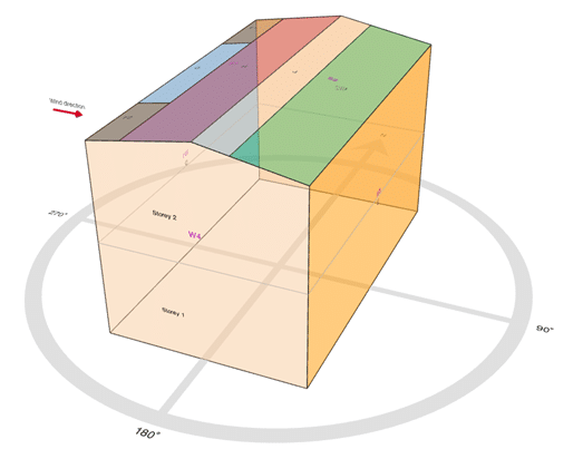
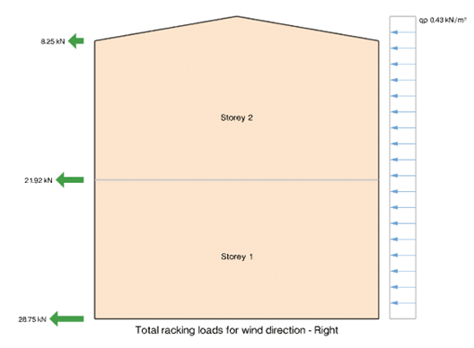
CADS Timber Racking Loads application calculates the horizontal racking loads acting on timber wall panels due to lateral wind pressures on multi-storey buildings. The calculations are carried out in accordance with EN 1991-1-4:2005 + A1:2010 (Eurocode 1 – Actions on structures – Part 1-4: General actions – Wind actions) and include the provisions of the UK National Annex.
The software determines the distribution of wind-induced forces on the building envelope and converts them into racking loads at each storey level, suitable for use in the design of timber wall panels in accordance with Eurocode 5.
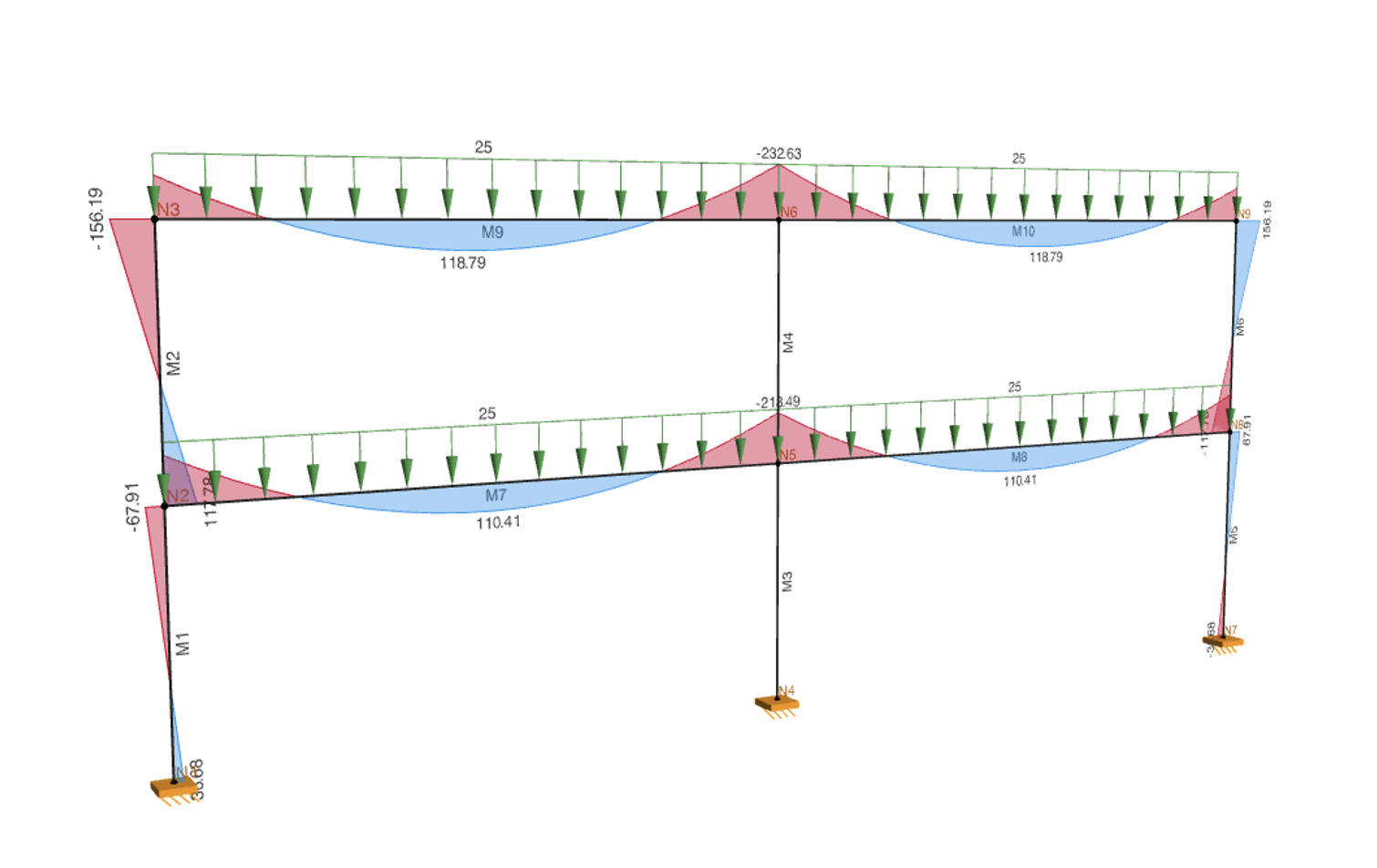
CADS 2D Frame Analysis is an application for performing linear static analysis of two-dimensional structural systems such as beams, trusses, portal frames, building frames, girders and general 2D assemblies.
The software provides an intuitive user interface for creating structural models using templates or manual inputs, running analysis and exporting results for use in structural calculation documents.
The program supports steel, concrete, and timber materials and allows users to specify member properties, loads, and load combinations.
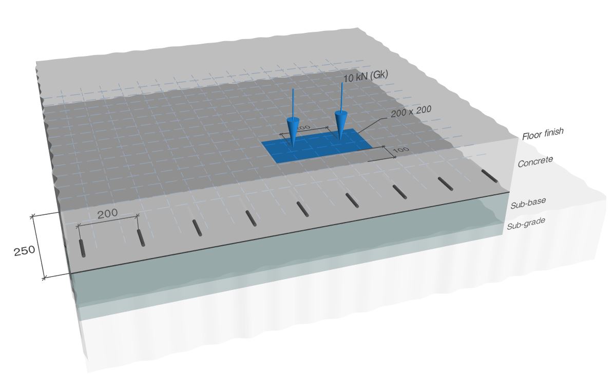
This software application has been designed to check the structural design of reinforced concrete ground bearing slabs subjected to point loads (single, double, quadruple), line loads and uniformly distributed loads, by calculating the resistance to bending moments generated by the loads and in the case of concentrated loads the resistance to punching shear. This is done in accordance with Technical Report 34 (TR34) – A guide to design and construction – Fourth edition (Published by The Concrete Society on August 2013, Reprinted June 2014 and March 2016).
The concrete slab can be reinforced using steel fabric or bar reinforcement, steel fibres, macro synthetic fibres or a combination of these.
Point loads can be applied either internally, at the slab edges or at the slab corners. In the case of edge or corner loading, load transfer can be allowed for using dowels, steel fabric or a proprietary system.
A user definable block library, as in CAD programs, allows the easy access and re-use of frequent structural systems.
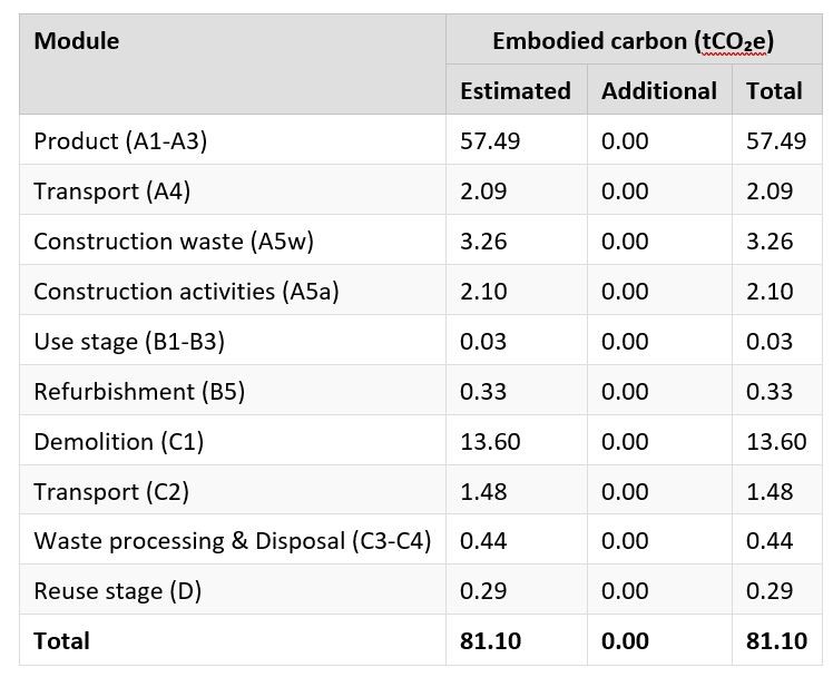
CADS Embodied carbon is a program for estimating the embodied carbon quantities for different structural schemes. The calculations are based on the recent guidance published by The Institution of Structural Engineers, How to Calculate Embodied Carbon (IStructE, 2020). The carbon quantities may be estimated at different stages of the design process by creating separate schemes for each stage. It is also possible to make alternative schemes for the same project to compare the carbon quantities across these different proposals so that the most environment friendly scheme may be chosen.
Input Options
The site address is entered using Google Maps, via a postcode or it can be manually entered.
Select the project stage and type from a list of preset variables, the design life. The program uses the life cycle stages as defined in BS EN 15978- 2011.
This application allows you to specify the schemes, their properties, additional carbon quantities and the bill of materials for each scheme.
Depending on the purpose, you can choose to calculate the embodied carbon for some or all of the life cycle stages.
You can create and evaluate multiple schemes using this application.
The user can specify the bill of materials for each scheme.
Output
The application works by fetching carbon factors associated with the materials you enter in the bill of materials.
This version of the application uses the carbon database found in The Inventory of Carbon and Energy (ICE), Building Services Research and information Association (BSRIA).
You can select the more commonly used materials and group them into a shorter list in the Preferred database for easy access. You can also add new materials to create your own database.
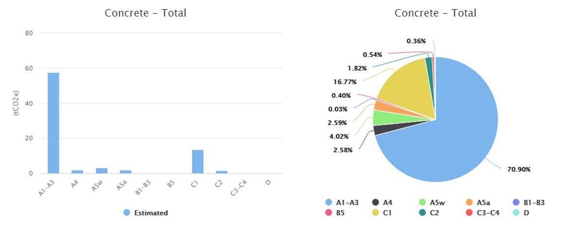
The estimated carbon from all the materials entered in the bill of quantities are plotted in different graphs and displayed under this tab. The Results graphs tab can display the graphical output for individual schemes or display comparison graphs across the different schemes. For each scheme, a collection of bar and pie charts showing the split of the carbon between the different material types, sections and life cycle stages.
For each scheme, a collection of bar and pie charts showing the split of the carbon between the different material types, sections and life cycle stages.
The Engineering Toolbox contains a collection of simple yet useful tools that a structural engineer may require whilst analysing or designing structures.

Crack Widths
This software application has been designed to calculate the crack width of concrete rectangular or T shaped cross-sections. The calculation is in accordance with BS EN 1992-1-1:2004 and NA to BS EN 1992-1-1:2004.
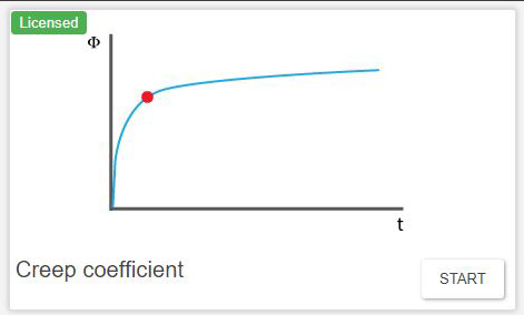
Creep Coefficient
This software application has been designed to calculate the creep coefficient of concrete. The calculation is in accordance with Section 3.1.4 & Annex B of BS EN 1992-1-1:2004 and NA to BS EN 1992-1-1:2004.

Foundation Depth for Building Near Trees
CADS Foundation Depth for Building Near Trees calculates the minimum foundation depth required to minimise the risk of damage to the structure due to volume changes of the surrounding soil. The calculations are performed in accordance with NHBC Standards 2020.
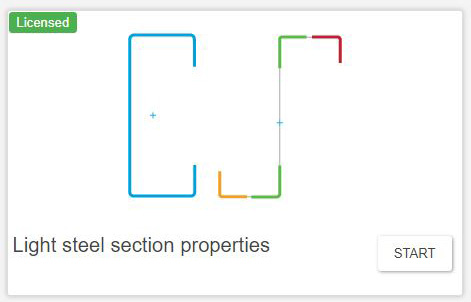
Light Steel Section Properties
This software application calculates the gross and effective section properties for cold-formed steel sections under bending and axial compression. The calculations are done in accordance with BS EN 1993-1-3:2006 – Design of steel structures – Part 1-3: General rules – Supplementary rules for cold-formed members and sheeting.
The effective section properties are calculated for Cold-formed sections of shape ’C’ sections (with or without lips) and ’Z‘ sections (without intermediate stiffeners).
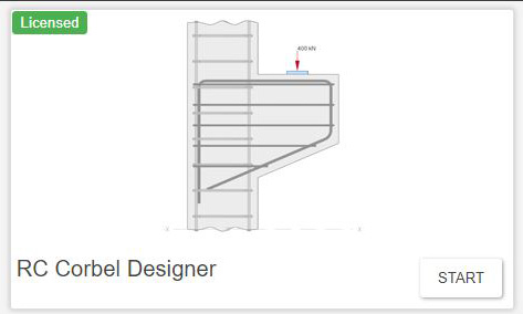
RC Corbel Design
CADS RC Corbel Designer is a program for design of a corbel subjected to vertical and horizontal loads. The design verification is based on Annex J.3 of BS EN 1992-1-1:2004+A1:2014 and the UK National Annex.
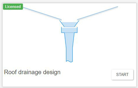
Roof Drainage Design
CADS Roof Drainage Design application calculates the capacity of various roof drainage elements in a roof drainage system. The calculation is done in accordance with BS EN 12056-3:2000 Gravity drainage system inside buildings – Part 3: Roof drainage, layout and calculation for UK National Annex and Manual for the Design of Roof Drainage Systems – A guide to the use of European Standard BS EN 12056-3:2000.
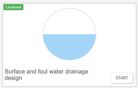
Surface and Foul Water Drainage Design
CADS Surface and Foul Water Drainage Design application calculates the size or capacity of surface and foul water drains. The calculation is in accordance with BS EN 16933-2:2017 Drain and sewer systems outside buildings – Design – Part 2: Hydraulic design and BS EN 12056-2:2000 Gravity drainage systems inside buildings – Part 2: Sanitary pipework, layout and calculation for UK National Annex.
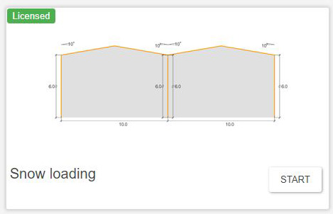
Snow Loading
CADS Snow Loading application calculates the snow load intensity for flat, monopitch, duopitch, and cylindrical roofs. The calculations are done in accordance with BS EN 1991-1-3:2003+A2:2015 [Eurocode 1 – Actions – on structures – Part 1-3: General actions – Snow loads]
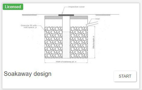
Soakaway Design
CADS Soakaway Design application calculates the dimensions of soakaway pit for various storm duration and also checks the adequacy of pit. The calculations are in accordance with BRE Technical Guidance 365: 2016.
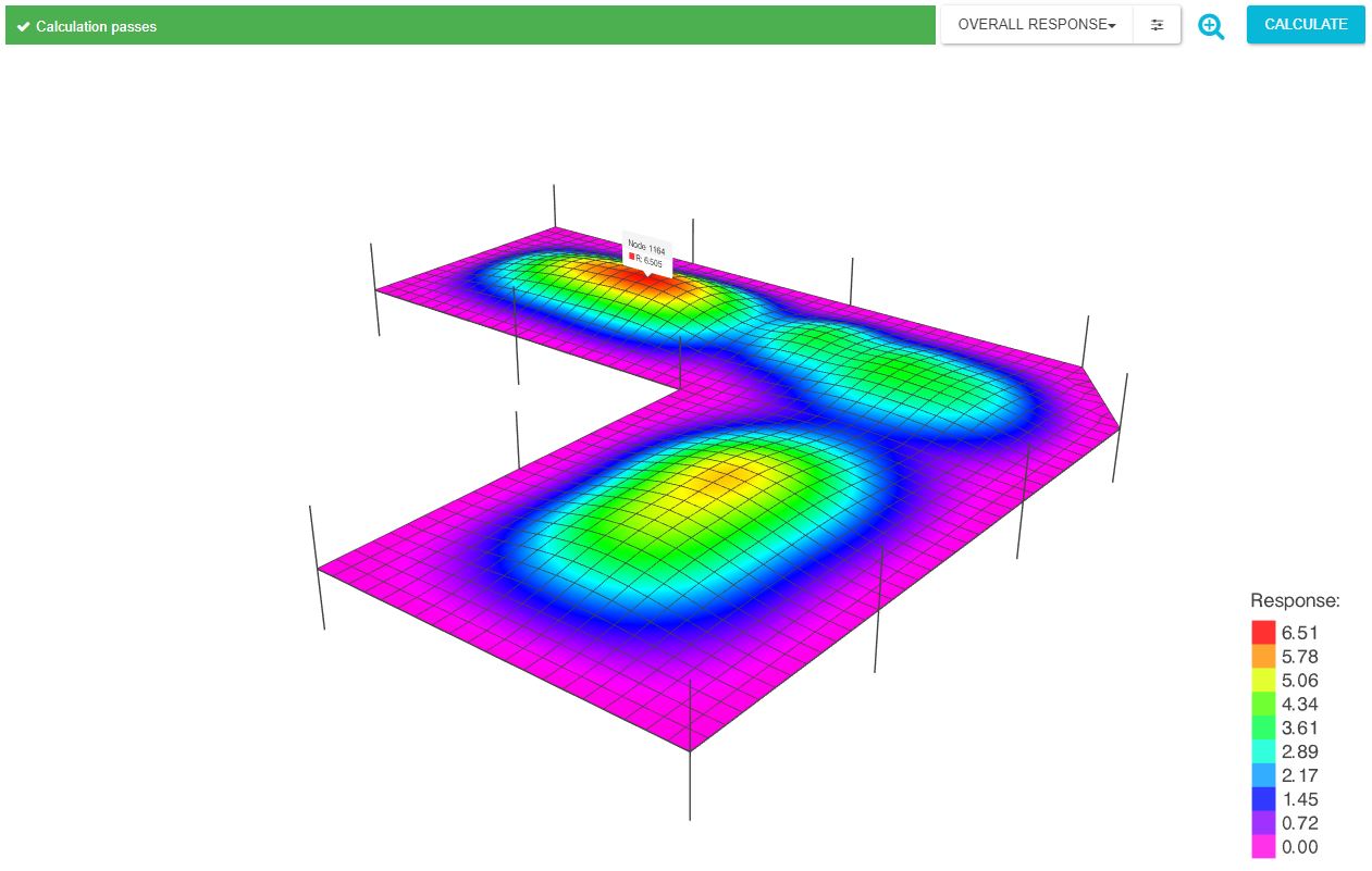
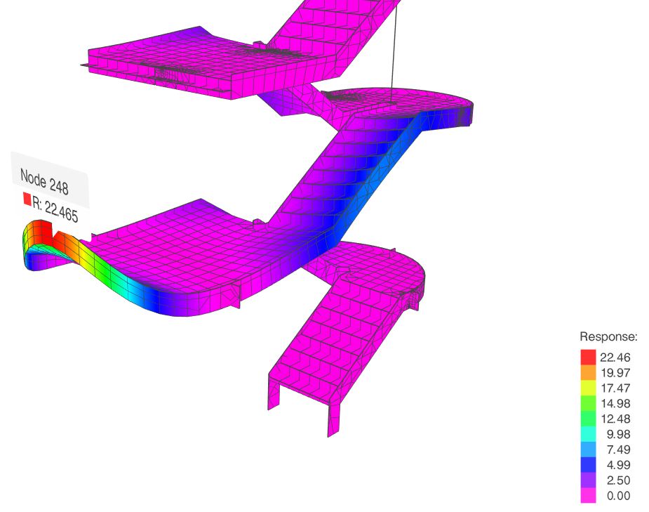
Footfall Analysis
CADS Footfall Analysis (CFA) is a post-processing software application which performs footfall analysis calculations for concrete slabs, composite floors and staircases using as input the geometrical and modal data from Dlubal RFEM and/or SCIA Engineer. To be able to perform a footfall response analysis using CFA, some features within the FE analysis software are required to be active/available, namely the Dynamics functionality.
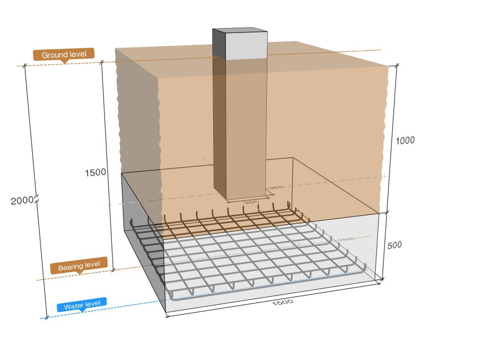
CADS Pad Base Designer is a program for checking and designing mass and reinforced concrete foundations based on BS EN 1992-1-1:2004+A1:2014 and BS EN 1997-1:2004+A1:2013 for UK National Annex.
Bases can be either Mass Concrete or Reinforced Concrete.
The program can run in check or design mode. Check mode means all the geometry and the footing dimensions entered are checked for the given loading. If the Design mode is selected, the software calculates the optimal footing dimensions for the given loading.
Loads can be applied as Axial or Horizontal loads and Moments in the x and y direction as defined by the base geometry.
There is a check for crack control which when enabled allows the user to specify the allowable crack width.
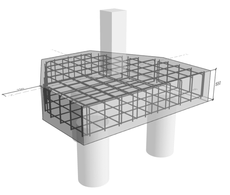
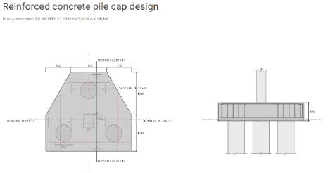
Calculation of pile caps for several pile arrangements are in accordance with BS EN 1992-1-1:2004+A1:2014 – Design of concrete structures – Part 1-1 General rules and rules for buildings for UK National Annex.
The program performs the analysis and design to find the appropriate size and reinforcement for a pile cap.
The application supports different types of pile configurations, from two piles to nine pile groups There is an option to calculate using Beam theory or Strut and tie model are supported.
Pile properties such as diameter, spacing factor and its ultimate capacity can be defined.
Supports axial loads and moments from two directions from a column.
There is a 3D and 2D preview of the pile cap with loading and reinforcement details.
Customisable output with 3 levels of output details, MS Word and PDF export of output reports.

CADS Punching Shear Designer is a software application which performs rapid punching shear calculations for reinforced concrete flat slab structures. In this version the calculations are generally in accordance with BS EN 1992:1-1:2004+A1:2014 (Eurocode 2: Design of concrete structures – Part 1-1: General rules and rules for buildings). This code is referred to as EC2 in the following.
The current version of the program may be used for reinforced concrete flat slabs supported on columns of rectangular, circular, elliptical, L, T or cruciform section. Once you have input the geometric and structural information, the program calculates the maximum shear stress at the control perimeters and checks against the allowable values and if required proceeds to calculate and arrange shear reinforcement in the form of shear studs.
The software produces output reports in the form of a brief summary or a more detailed report, which may be displayed on screen, printed or exported to MS Word or PDF to suit your requirements.
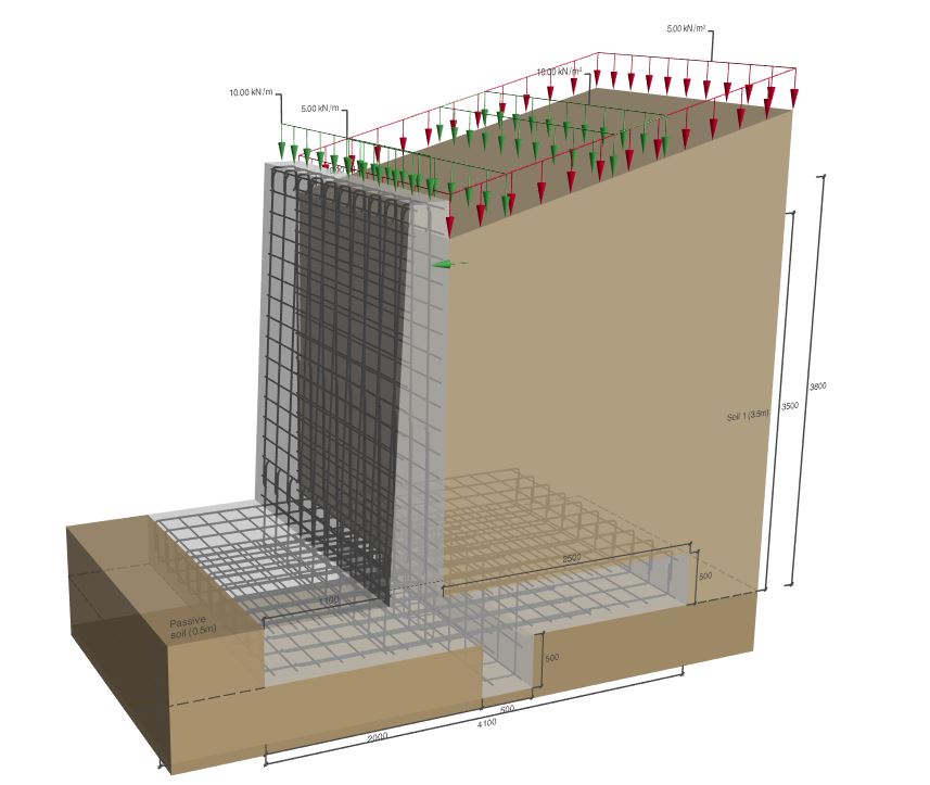

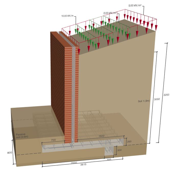
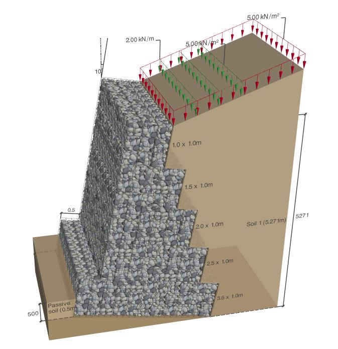
CADS Retaining Wall Designer is a computer program intended to assist the geotechnical and structural design of free standing gravity and semi-gravity retaining walls using Eurocode guidance where applicable. Several related design codes and publications have been consulted as listed in the references in section 6 of this guide and in some cases new solutions have been developed as far as possible in accordance with the general principles of the design codes.
The program provides an analytical tool, not a direct design process. It remains the user’s responsibility to assess soil conditions and strength parameters and to select the appropriate structural materials, dimensions and design parameters.
The program organises the input data and output results in such a way that you are led to consider all the relevant parameters in a logical and complete manner. The calculations, which are tedious, confusing and prone to error when carried out by hand, are completed accurately in moments by the program, allowing you to consider alternative parameters and arrangements with ease and confidence.
After finishing the calculations, a brief message at the top of the window is shown to indicate adequacy or failure of the retaining wall. A summary of input data and calculation results is displayed in the Calculation Summary Report. Detailed line by line calculations may be viewed and if necessary, printed by selecting the Calculations Report option to show logic, equations and their results and by selecting Detailed Report, the numerical values are shown as substituted in the equations.
The current version of the software contains three modules for the design of:
- Reinforced concrete retaining wall
- Unreinforced Masonry retaining wall
- Reinforced masonry retaining wall
- Gabion retaining wall
Each of the above sections are complete in themselves and may be read independently without cross referencing.
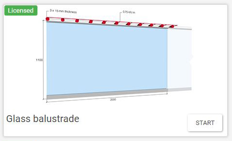
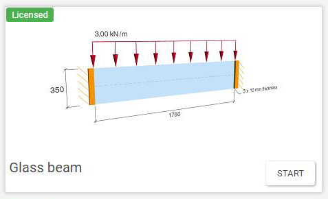
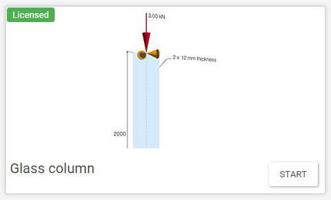
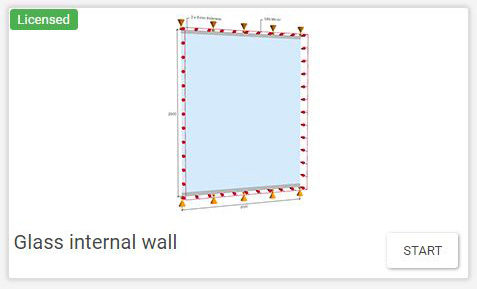

CADS Structural Glass Designer is a program for checking the structural design of specific glass elements by preparing calculations in accordance with the current guidance, Structural use of glass in buildings (2nd edition). Where the guide did not provide adequate guidance, other publications have been consulted as listed in the references and in some cases new solutions have been developed as far as possible in accordance with the general principles of the codes.
The program organises the input data and output results in such a way that you are led to consider all the relevant parameters in a logical and complete manner. The calculations, which are tedious, confusing and prone to error when carried out by hand, are completed accurately in moments by the program, allowing you to consider alternative parameters and arrangements with ease and confidence.
After finishing the calculations, a brief message at the top of the window is shown to indicate adequacy or failure of the glass element along with a summary of results displayed in the Calculation Report Summary page. More detailed results may be viewed in the subsequent Detailed page of the Calculation Report.
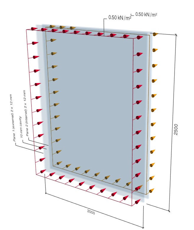
NEW!! – Insulated glass units
Calculations are based on the framework presented in BS-EN 16612:2019. The software considers the consequences arising from the presence of a fixed and hermetically sealed quantity of gas within the cavity (or cavities) of the insulated glass units.
Performs the structural strength and deflection checks of insulated glass units (double and triple glazed).
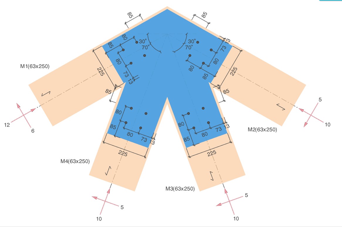
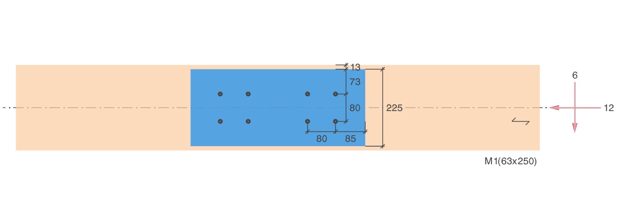
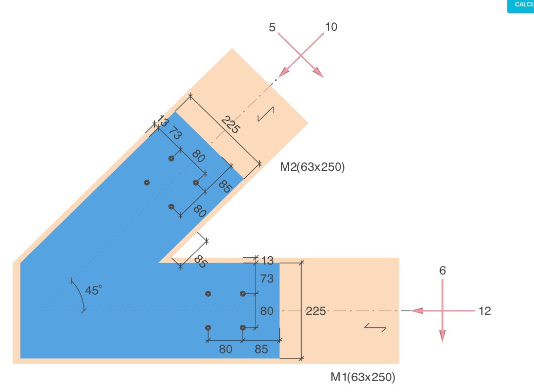
Calculation
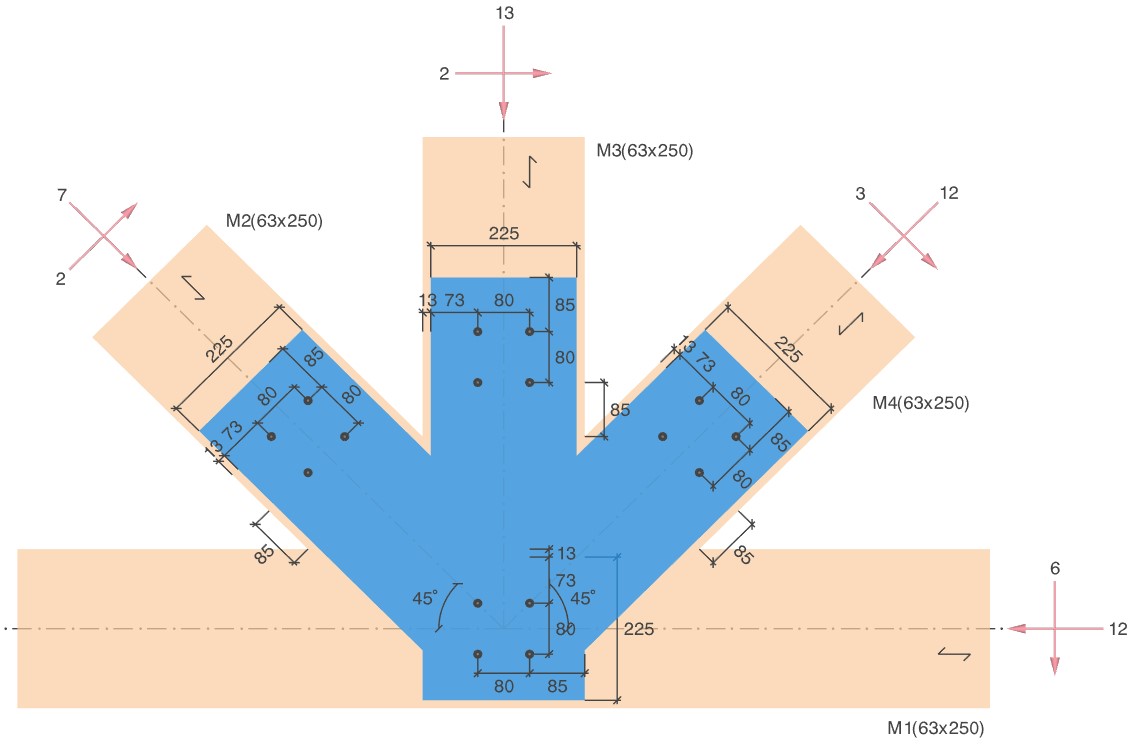
- Calculations are in accordance with BS EN 1995-1-1:2004+A2:2014 – Design of timber structures – Part 1-1 General Common rules and rules for buildings for UK National Annex.
- Verifies the capacity of the connection, connected members, gusset plates and fasteners.
Input
- Software supports different types of connections splice, apex/corner, and intermediate (with and without gusset plates);
- Different types of fasteners are supported based on connection types;
- Member properties such as material, cross-section and its orientation can be defined;
- Allows entry of factored axial, shear and moment loading along with the load duration.
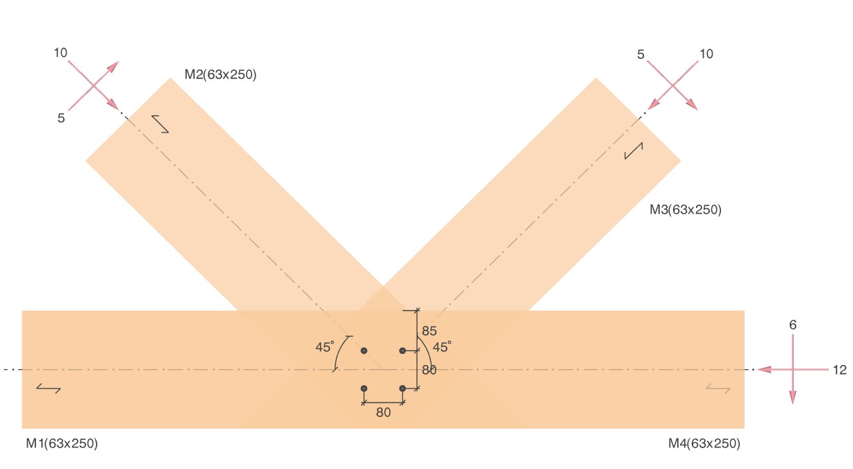
Output
- 3D and 2D preview of the timber connection with loading details;
- Customisable output with 3 levels of output details;
- MS Word and PDF export of output reports.
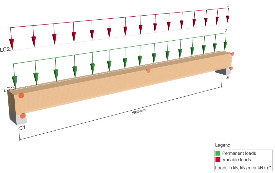
CADS Timber Beam Designer is a program for design of a timber beam based on BS EN 1995-1-1:2004+A2:2014 – Design of timber structures – Part 1-1 General – Common rules and rules for buildings for UK National Annex.
Calculation
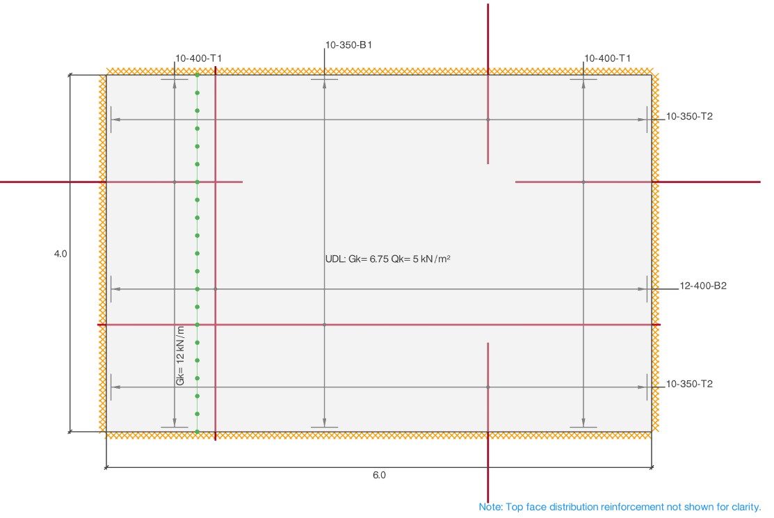
This software performs structural design of rectangular slab panels that are essentially two-way spanning between a system of supporting beams or walls:
- Calculations are based on Johansen’s Yield Line theory published by the Cement and Concrete Association in 1962 and BS EN 1992-1-1: 2004;
- The serviceability deflection check is carried out using the span/effective depth limits given in EN 1992-1-1 and the UK NA.
Output
- 2D view of the two-way slab in a planar view showing the dimensions, loadings and, where applicable, reinforcement arrangements
- Customisable output with 3 levels of output details
- Numerical and/or formulae output for easy checking and presentation
- Easy sharing option by printing, exporting to file in MS Word or PDF format
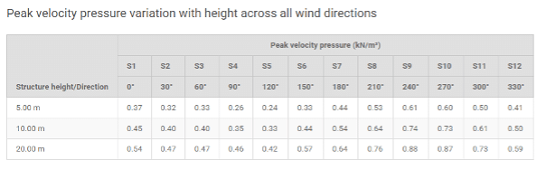
Calculates peak wind velocity and wind pressure to design standards for the UK, Ireland and USA.
Wind loads are calculated for 4, 8 or 12 different directions and at various heights.
The user can select the site location on the map using a mouse pointer or use the search bar by entering the location, postcode or partial address.
Site wind velocity and distance to the shoreline are also automatically calculated.
Wind sector, orography and terrain information can be defined.
Option to view the wind velocity contours over the map for supported regions.
It is also possible to configure the height bands at which pressure is calculated.
There is either a 3D or 2D preview of the map, and a pressure variation with height graph for all wind directions. Output choice of 2 levels of details, and the option to export to MS Word and PDF output formats.
CADS Wind Load application calculates wind load intensity for flat, monopitch and duopitch roofs, and canopies.
The calculations are performed in accordance with EN 1991-1-4:2005+A1:2010 [Eurocode 1 – Actions – on structures – Part 1-4: General actions – Wind actions].

3D View of Duopitch Roof Showing Zones
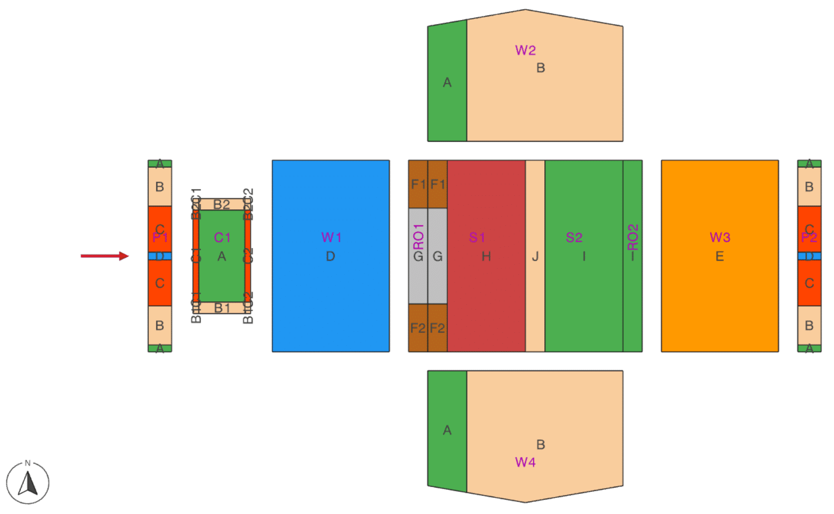
2D View of Zones
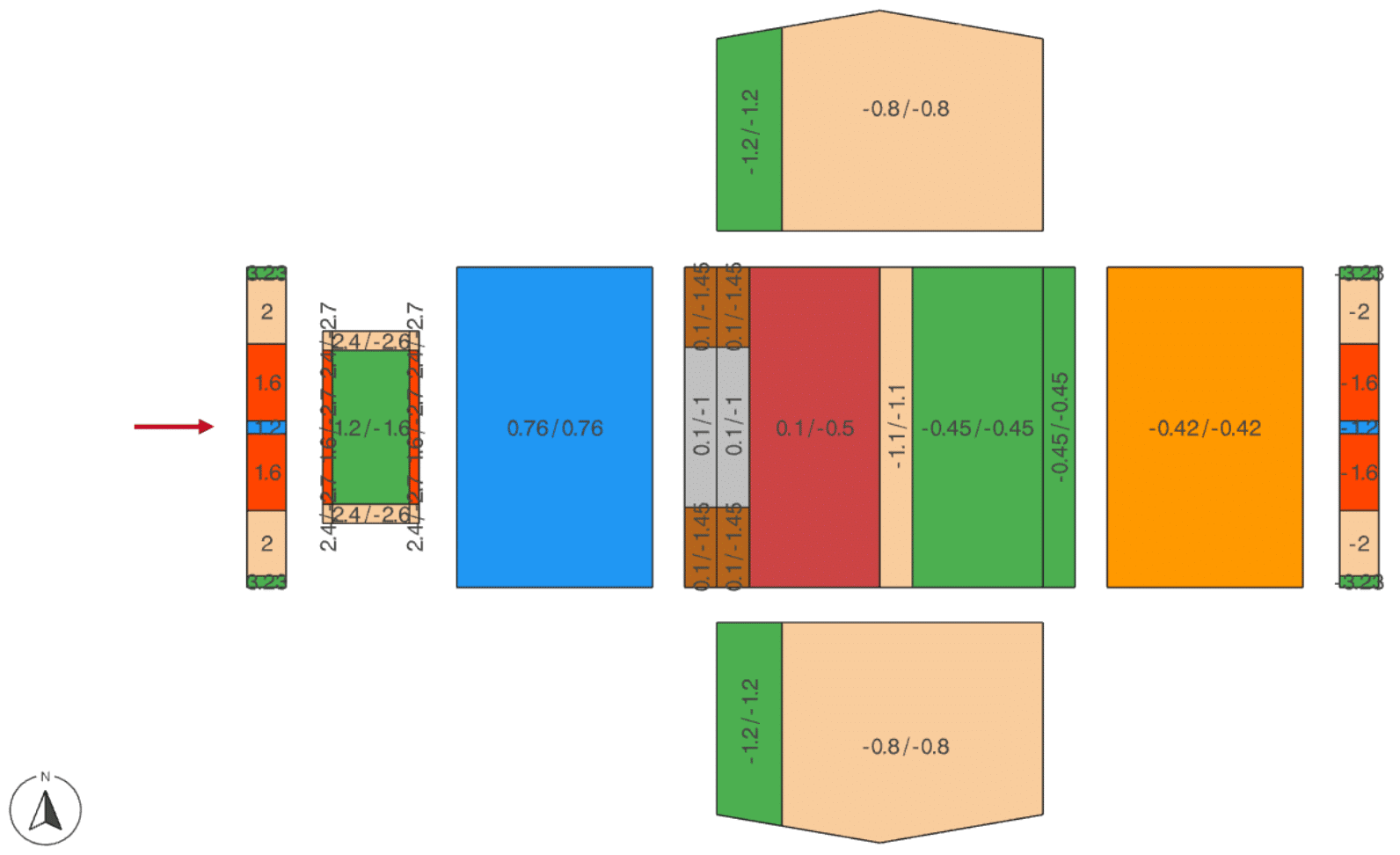
2D View of Calculated +/- Coefficients
Request a Trial for CADS Hub
Request your free trial now to see a restricted version of CADS Hub. If you want to purchase an app, you can do it all within the Hub.
Prices start from £495 + VAT.