CADS Dlubal RFEM Features
RFEM In a Nutshell!
Features and Benefits At-A-Glance
See below the typical list of processes for a computerised design workflow and the key features provided for each stage.
Intuitive CAD Tools
Dlubal RFEM uses CAD-like tools such as object snaps, drag-and-drop, even copy/paste to input geometry and other project data. Right-clicking on a structural object activates the shortcut menu, which facilitates the ease of creating or editing such objects. The user interface is very intuitive thus reducing the time required to learn the program and input a project model.
A user definable block library, as in CAD programs, allows the easy access and re-use of frequent structural systems.
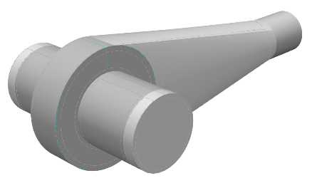
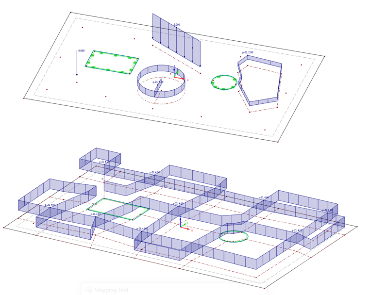
Complex Shapes and 3D Solid Finite Elements
Curved members and surfaces with variable thickness can be modelled. Complex 2D and 3D surfaces can be created using a linear or rotational extrusion tool. For the connection of surfaces, RFEM automatically generates the intersection geometry between surfaces such as cylinders.
3D Soild Elements are useful for modelling structures that do not suit the use of plates and shells such as complex connections, retaining walls and mechanical objects.
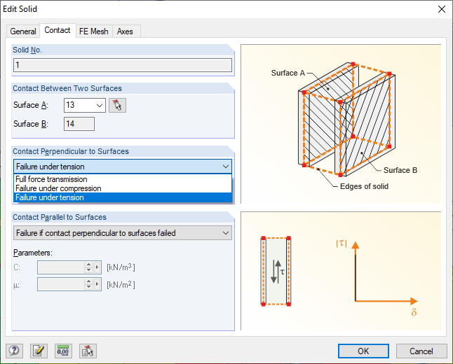
Contact Solids
In RFEM a Contact Solid is used to define certain contact properties between two surfaces.
It allows for the modelling of two solid surfaces touching vertically or lying on top of each other. With a Contact Solid these plates can therefore be made to only displace if in tension or compression.
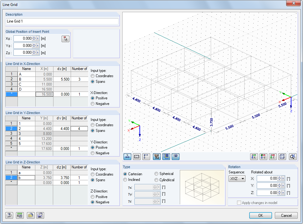
Grids and Guidelines
Whilst not essential for modelling, user-defined 2D or 3D grids or guidelines can help you to model appropriate structures. The intersection points of the grid provide insertion points for surfaces and members and can be either cartesian, inclined, spherical or cylindrical.
A timesaving tool for editing a structure is the capability to “attach” the grids to the model. Then if there are any changes to the grid dimensions the model will update too.
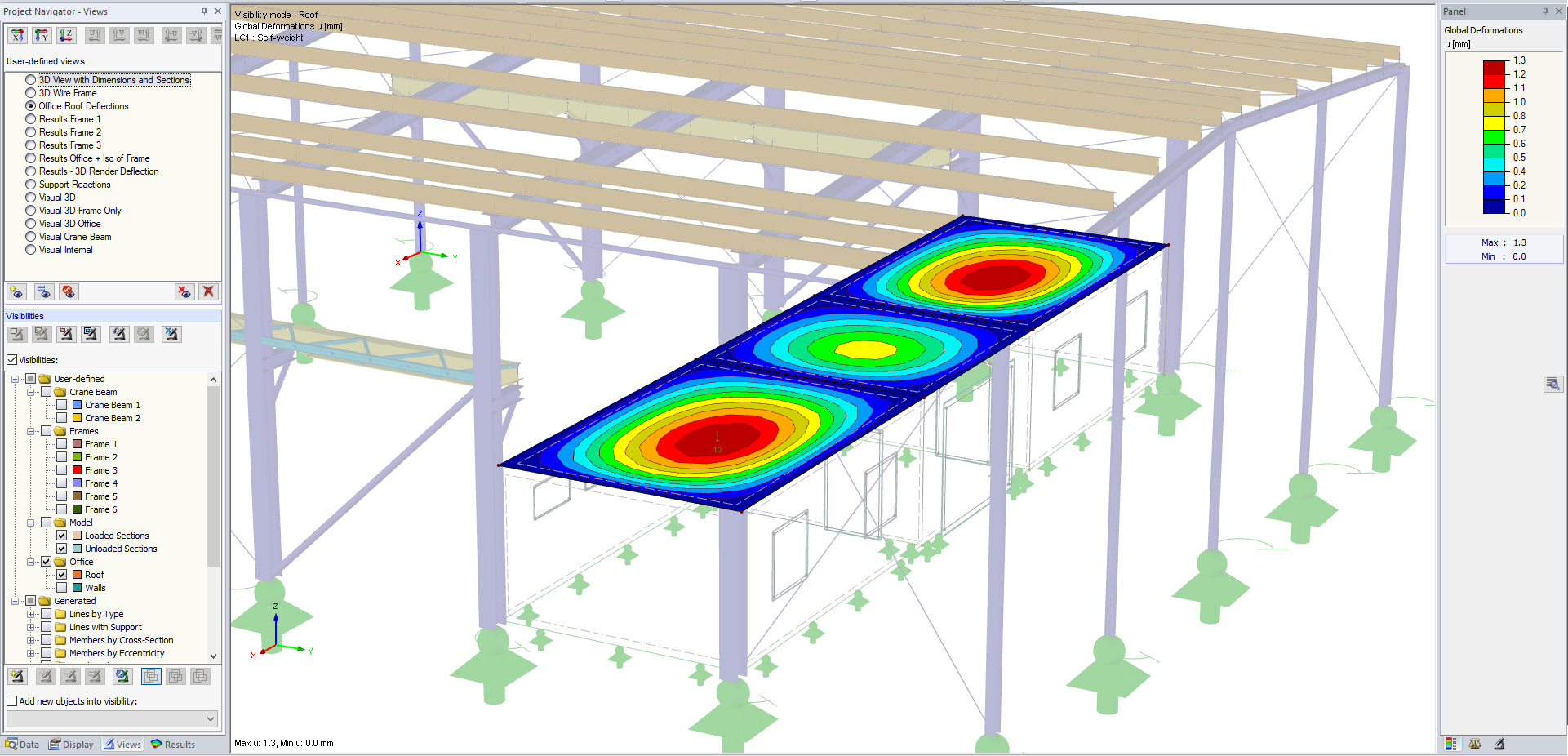
View Filters and Selection Tools
User-defined views make modelling and the results evaluation easier. By using view filters, you can divide the model into partial views that fulfil certain criteria. It is therefore possible to only activate the surfaces of a plane or members with a particular cross-section or material for the display. These options can be used both for the evaluation of results and for the for the input of a model or load data.
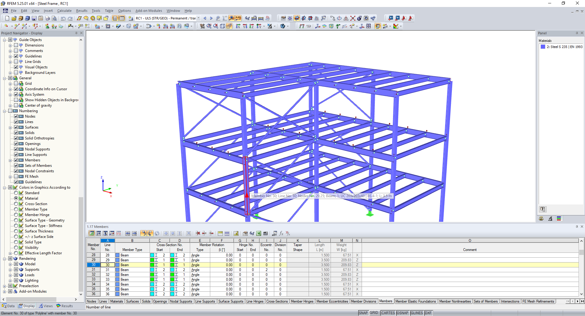
Table Input
The Table panel sits at the bottom of the screen and can be turned on permanently or as required.
In the Tables panel there are 4 icons to select from:
– Model data
– Load cases and combinations
– Loads
– Results
Any of these data forms can be updated or edited to change the project model. This is sometimes easier than more direct methods.
Details can be input and exported to EXCEL, this data can be a selection of several data categories or a select few items. Clicking on a Table value will annotate the model with any value selected such as a nodal displacement or location, highlight a cross-section type, a load case or a result value.

Parametric Modelling for frequently occurring structures
For modelling of frequently occurring structure types, RFEM provides parametric input. Models can be created by inputting the values of predefined model parameters such as geometry, section types, loads etc. The input table thus created can then be used for generating similar models at another time by entering new values of these parameters.
Support Nonlinearity, Line and Nodal Releases
Create realistic models, no need to compromise, with modelling tools for nodal or line supports and member and surface fixities.
Supports with varying action types can be assigned such as load deflection values, spring properties or assigned to lift-up to represent base anchorages that only act in compression.
One-way spanning slabs. Line releases, which amongst other things, can allow a disconnect of the vertical support. Applying this feature to the required free edges of a slab sitting in a frame of members will make it span one-way.
Nodal releases allow members where in contact to separate from each other either in tension or compression.
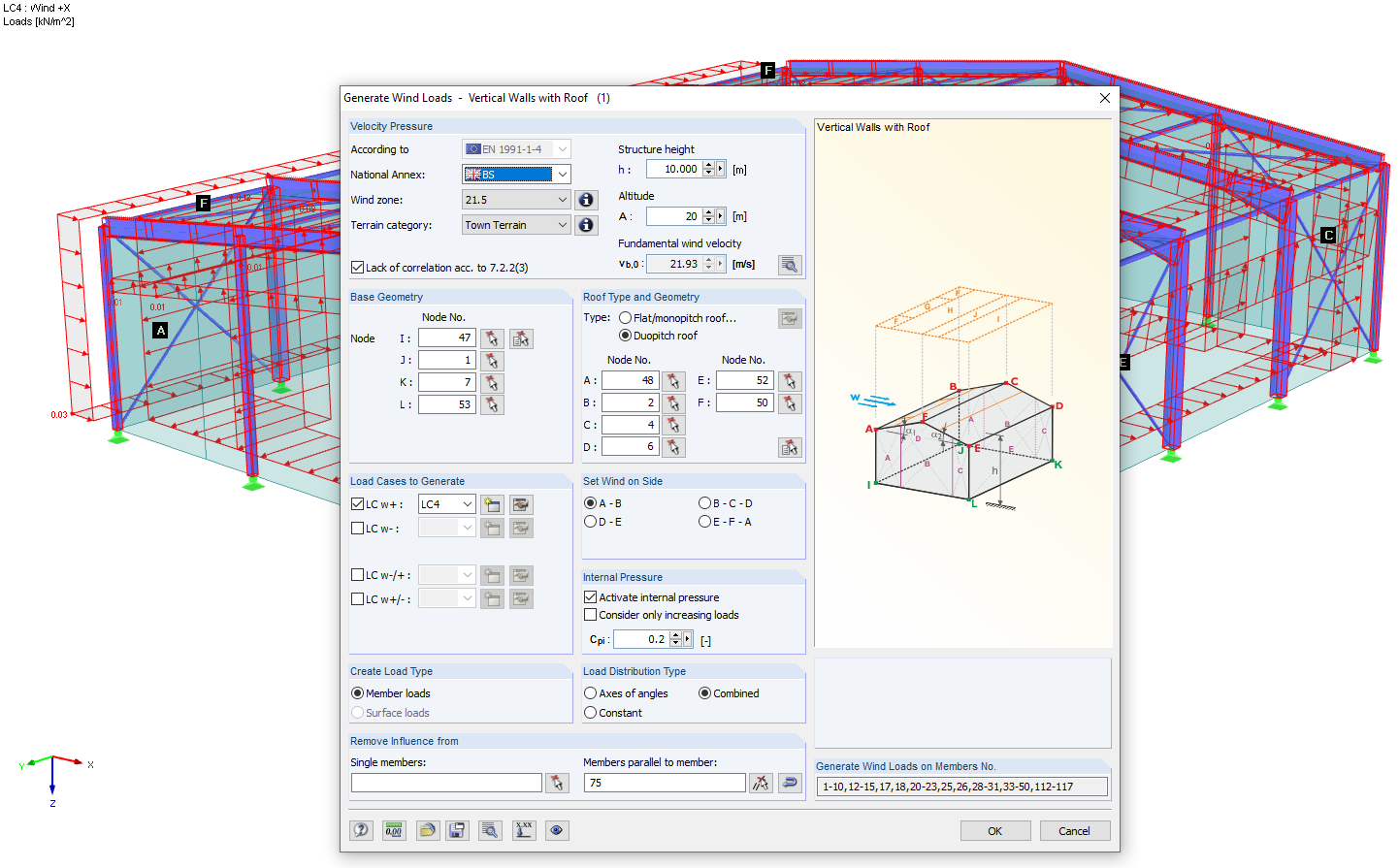
Wind & Snow Loads
Wind and snow loads, including drift load, can be automatically generated as member loads or area loads on the following structural components (optional internal wind pressure for buildings with openings):
– Vertical walls
– Flat roofs
– Monopitch roofs
– Duopitch/Troughed roofs
– Vertical walls with roof
RWIND
A computerised wind tunnel! The generation of Wind Loads On Any Type of Structure!
RWIND Simulation is a stand-alone program for numerical simulations of wind flow (digital wind tunnel) around buildings or any other objects and generating wind loads, i.e. forces acting on these objects.
This program can be used as a stand-alone application or as a complement to RFEM for static and dynamic analysis.
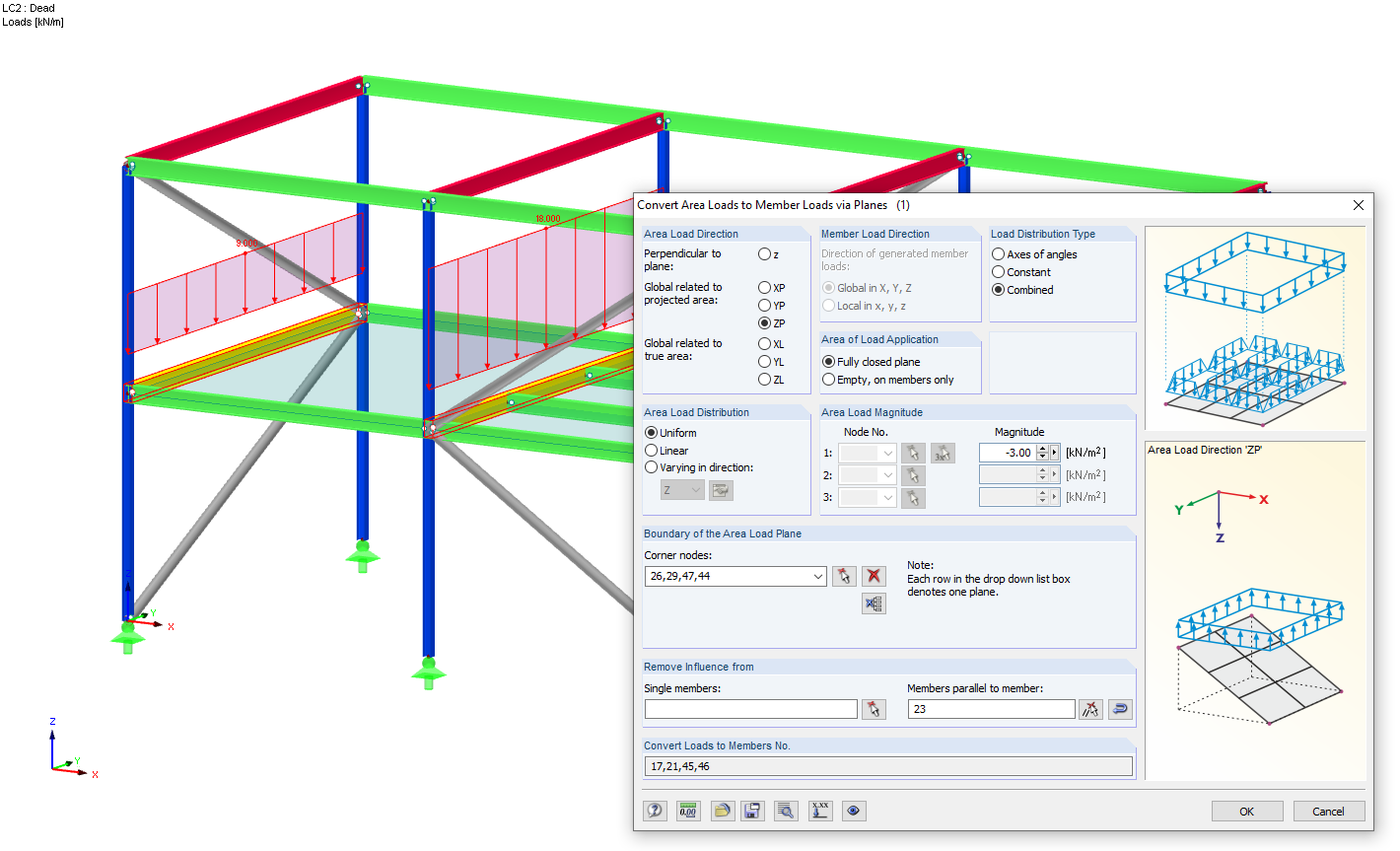
Structural Load Generators
Area loads can be assigned to any plane of members, vertically, horizontally, or inclined, in the local or global direction, uniform or varying in size. These area loads are then converted to member loads. It is possible for the same area load, either initially or later to edit it, to specify the action of the area load as two-way or one-way spanning.
Area loads on openings can also be converted to line loads around the opening.
Member coatings, such as ice, can also be converted to line loads on the member.
Surface loads can be applied as uniform or varying values within boundaries of a polygon or circular structure.
Simple Loads and Free Loads
There are various load types available for member and surface loading, (force, moment, temperature, settlement, pre-camber and others). In the case of imperfections for 2nd order analysis, inclination and pre-camber can be determined according to the Eurocode.
Loads can be easily edited, moved, copied between members or surfaces, or, by using a simple double click, edited by value or load case.
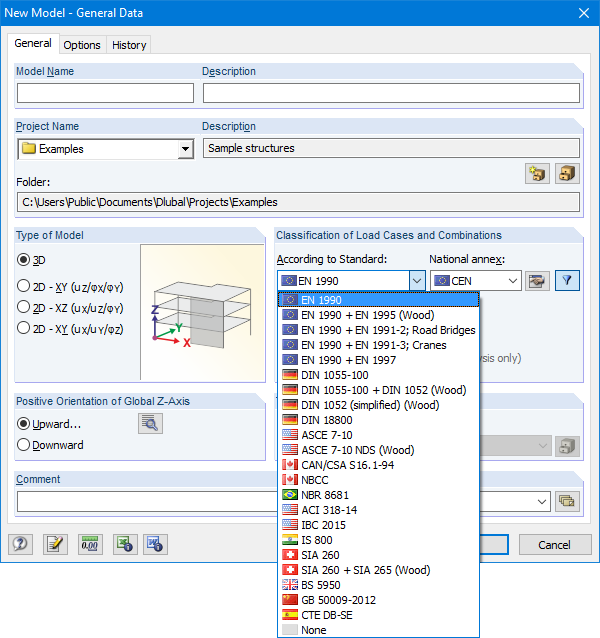
Automatic Load Combination Generator
RFEM provides automatic generation of load and result combinations according to Eurocode and other international standards in compliance with the corresponding combination expressions. In a clearly arranged window, you can copy, add, or renumber load cases. There are also options available for the reduction of automatically generated combinations.
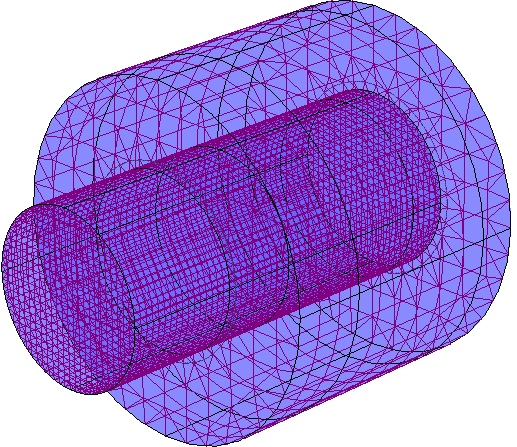
Basic FE Mesh & Refinement Tools
If no FE mesh refinements have been defined, the FE mesh is generated with user defined target FE length. Mesh elements can be defined by the user as either quadrangles or triangles, or both.
You can use FE mesh refinements to influence the mesh generation for specific areas. With this, a user-defined discretisation is done either around a node, along an edge or a chosen surface.
The Adaptive mesh refinement function allows you to automatically create refinement areas in the FE mesh, in which case you do not have to manually define FE mesh refinements.
A timesaving display function for the FE mesh quality is included with RFEM. An internal check is done of the created FE elements for defined criteria, the result of which can be displayed graphically. It will be displayed in three different colours to illustrate the different levels of quality. You can edit all values of the criteria and thus adjust them to your individual needs.
Multi-Core Processor and 64-Bit Technology
The equation solver includes an optimised FE Mesh generator and supports the latest multi-core processor and 64-bit technology. Therefore, you can perform parallel calculations of linear load cases and combinations by using several processors without additional random access memory (RAM). The stiffness matrix has to be created only once. The 64-bit technology and the enhanced RAM options allow for calculation of complex structural systems using the fast and direct equation solver.
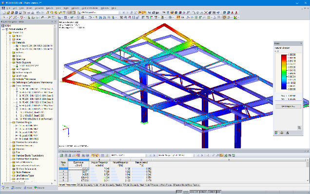
Dynamics Including Dynamic Response/Footfall Analysis
Watch our CADS Footfall Webinar
Typical application areas for dynamic analysis are seismic design, vibration design of buildings, calculation of machine foundations as well as natural frequency analysis of bridges and chimneys.
– Dynamic analysis of natural frequencies and mode shapes of member, surface, and solid models.
– Dynamic and seismic analysis including time history analysis and multi-modal response spectrum analysis
– Seismic and static load analysis using the multi-modal response spectrum analysis
– Nonlinear dynamic analysis to external excitations
CADS Footfall Analysis (CFA) is post-processing software that is used in conjunction with Dlubal RFEM to provide footfall response analysis calculation. Footfall response is of interest to users concerned about the vibration induced in their structures due to walking related activities. As advances in structural design result in more efficient and lighter irregular structures, sensitivity to vibration of the structures is becoming increasingly significant.
Construction Stages
The construction stages feature allows for design of all forms of RFEM models considering the construction stage during the building phase.
Negligence of the construction stage influence may cause errors in the calculation of entire models. RFEM analyses internal forces and displacements at each phase and creates design envelopes of results. The design therefore considers all maximum forces for design over the entire construction.
Geometric and Material Nonlinearities
In RFEM it is possible to consider member nonlinearities, (for example compression/tension only, slippage, tearing, creep), as well as support and release nonlinearities such as failure, creep, friction support, and so on.
In addition to linear static analysis and second-order analysis, P-delta and p-delta deflections accounted for by global and bow imperfections, there is also large deformation analysis available for the design of cables and membranes. Moreover, RFEM supports the consideration of material nonlinearities such as plastic hinges for members, general material plasticity for surfaces, concrete cracked section analysis, and many others.
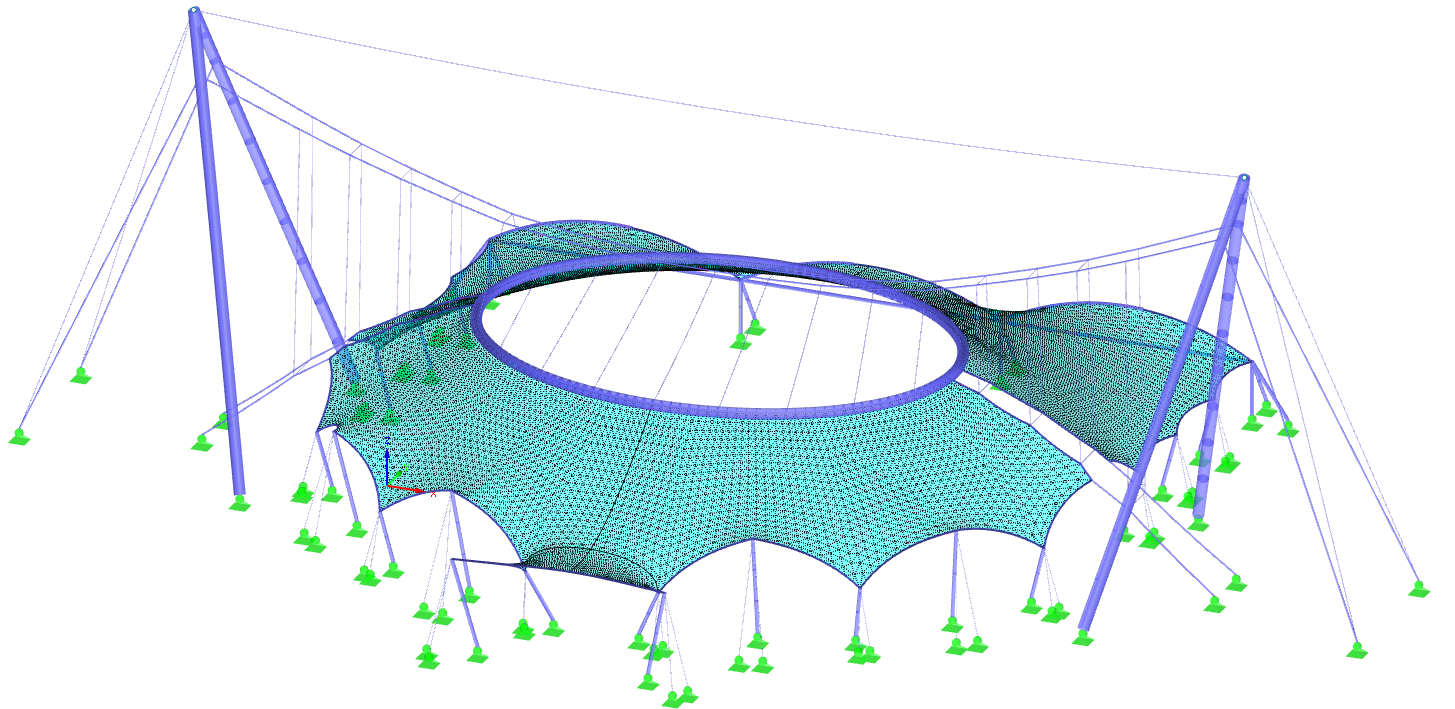
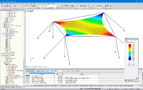
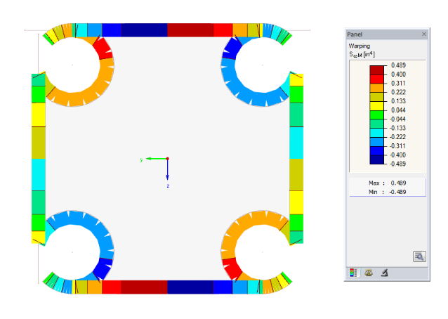
Form-Finding and Generation of Cutting Patterns for Membrane Structures
The form-finding feature determines equilibrium shapes of membrane and cable elements in RFEM. In this calculation process, the program searches for a geometric form in which the surface stress/prestress of membranes and cables is in equilibrium with natural and geometric boundary conditions. This process is called form finding.
RFEM can also generate cutting patterns for membrane structures. Boundary conditions of the cutting patterns on curved geometry are determined by boundary lines and independent planar cutting lines or geodesic cutting lines. The flattening process is performed according to the minimum energy theory.
For each pattern compensation can be applied in the warp and weft direction. It is possible to set a special compensation value for each boundary line as well as overlaps for manufacturing processes.
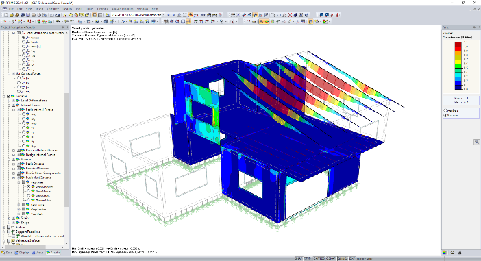
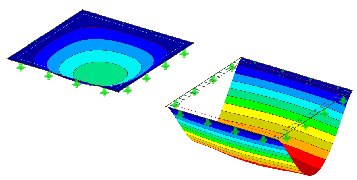
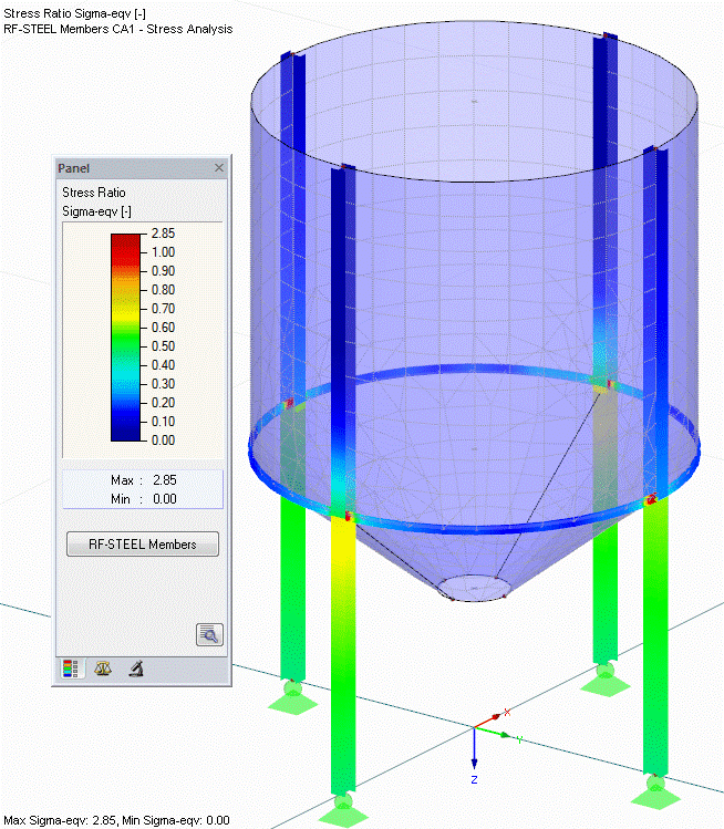
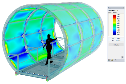
Displacements, Internal Forces and Stresses
Deflections, internal forces and stress results can be displayed on the model in a variety of forms chosen by the user to suit the results. Colours within the member, with hatching or for surfaces at isolines or isobands, all with or without result values or just the extreme values.
RFEM displays the maximum stresses and stress ratios selected by either cross-section, member or surface. The result values are also presented in on-screen tables, the user can click on a value to see it highlighted in the model above.
Right click on any member and RFEM will produce a set of result diagrams for any values providing a detailed review. Sections can be drawn on surfaces so results can be displayed in a 2D graph.
Configurable Results and Graphics
It is possible to individually adjust the colours, label size and formats of results to suit the user. Contour diagrams can also be edited, their colours and result intervals can be edited, or input a range of values for the display.
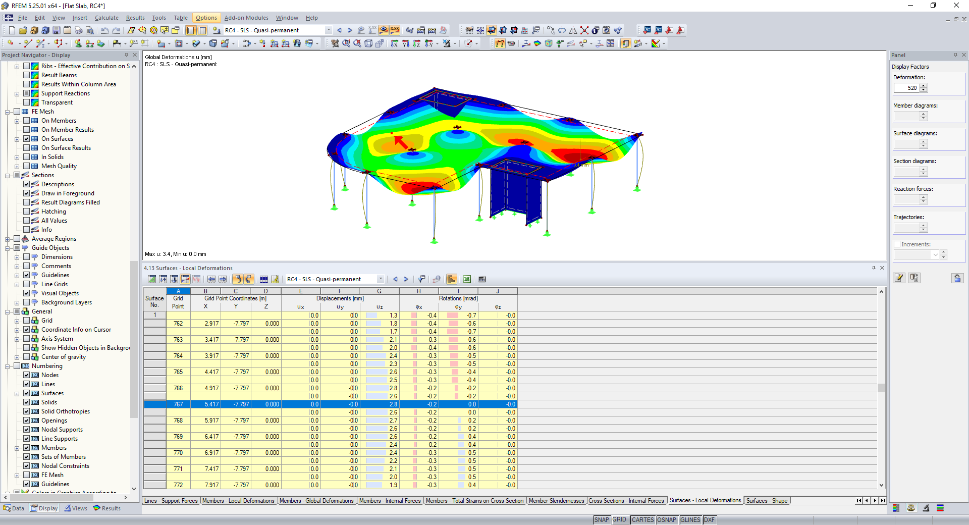
Tabulated Results
For the occasion when the results required can be more easily obtained from a simple table. The selected value that is under review once highlighted can be seen in the graphic view above.
Filters are available for the results as well as sort options. The table contents can be selected by graphically picking the region of the structure required. A coloured relation scale shows quicky max and min values. All information can be output directly to Excel.
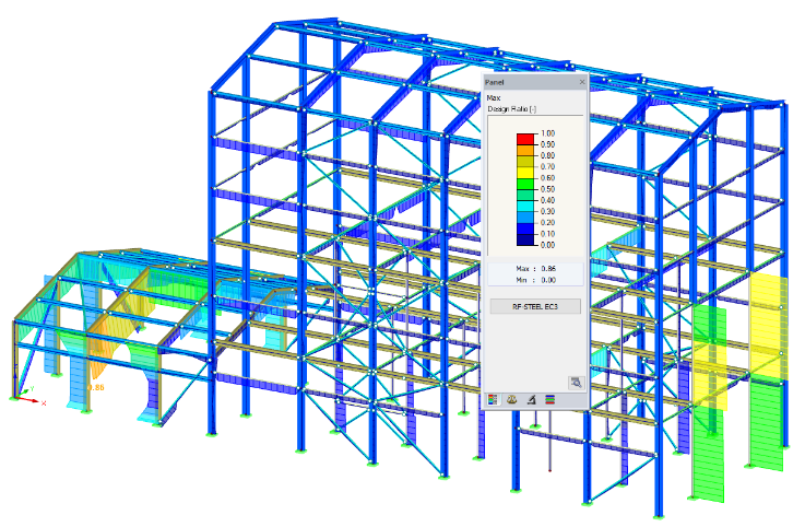
Steel Design
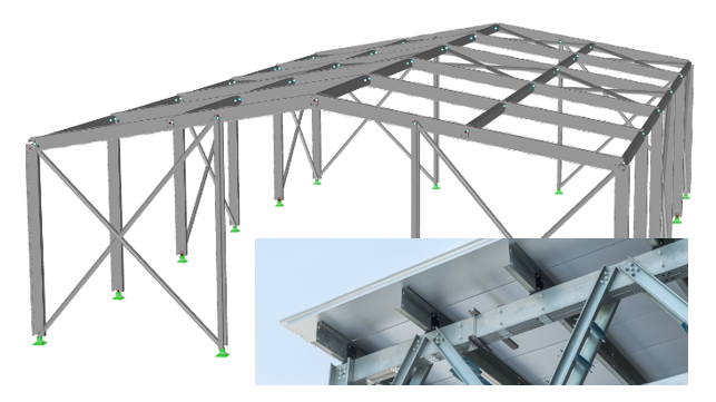
RFEM performs all characteristic designs of the ultimate and serviceability limit states as well as stability and deflection analyses, fire resistance check, for steel members according to the Eurocode EN 1993. Other national codes are available.
The program can design steel structures such as steel buildings, steel halls, scaffolding, bridges, silos, cranes, crane runways, masts, winter gardens, etc.
Members can either be checked for capacity or automatically designed for optimum section size. Results are displayed graphically on the model.
The range of member types is extensive and includes members that are tapered or with holes, unsymmetric sections, pairs and built-up sections as well as welded profiles (welds are designed also in this case). Non-standard sections can also be user input and checked. For Cold formed Steel sections, which can also be designed, see section below for more details.
Members can be checked for either an elastic or plastic analysis, second order analysis, for tension, compression, bending and shear as well as torsion and warping torsion. Buckling and lateral torsional buckling checks also performed, (later torsional restraints can be input as required).
Effective lengths are given by default, can be user input or calculated automatically by the program which will run an analysis to accurately calculate the true buckling lengths.
Cold Formed Steel Design
Available for cold-formed L, Z, C, channel, top-hat, and selected manufacturers sections such as Metsec. These are all accessible from the cross-section database which can be edited and added to. It is also possible to develop a clients’ own user defined cold-formed cross-sections.
Determination of the effective cross-section considering the local buckling and the distortional buckling.
Cross-section ultimate limit state, stability, and serviceability limit state designs according to EN 1993-1-3.
Design of local transverse forces for webs without stiffening, and stability analysis according to the second-order analysis as stress analysis including consideration of the 7th degree of freedom (warping).
Steel Plate Design
RFEM performs plate design using general stress analysis, calculating the existing stresses and comparing the results with limit stresses.
In addition there is the option of an automatic optimisation of thicknesses including the export of modified cross-sections back to the model for re-analysis.
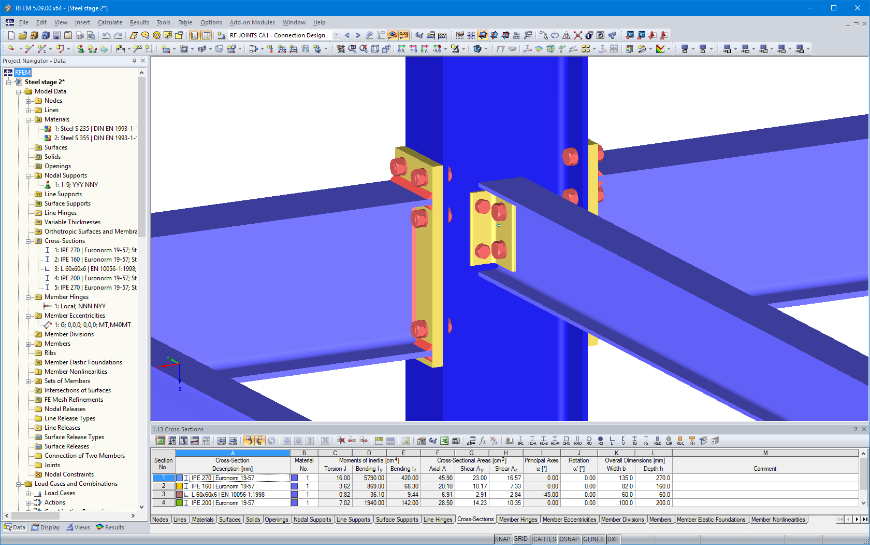
Steel Connection Design
Types of steel connections include rigid and pinned beam connections, column bases, hollow sections, and tower connections. These connections can all be designed according to Eurocode 3 from within a steel structure.
For rigid connections types are beam to column joint with end plate, rigid end plate connection as beam joint and rigid splice plate connection. It is possible to apply stiffeners, supplementary web plates, and backing plates, and to check the geometrical feasibility of a connection with respect to power tools to be used for tightening bolts.
For simple connections, there are four different types, web cleat connection, fin plate connection, short end plate connection, and end plate connection with cleat.
RFEM will also design tower connections, nominally pinned bolted connections used in lattice towers. There is an extensive range of joint types, for example bolted connection of diagonals without gusset plate 2D, bolted connection of diagonals without gusset plate 3D, bolted column joint and T-, K- and KT-joints for the connection of diagonals.
RFEM will automatically classify the connection and identify it as semi-rigid if applicable. In this case the frame analysis needs to be modified, the connection joint is updated to a hinge with its actual rotational stiffness as calculated by the joint design.
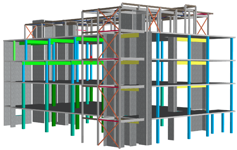
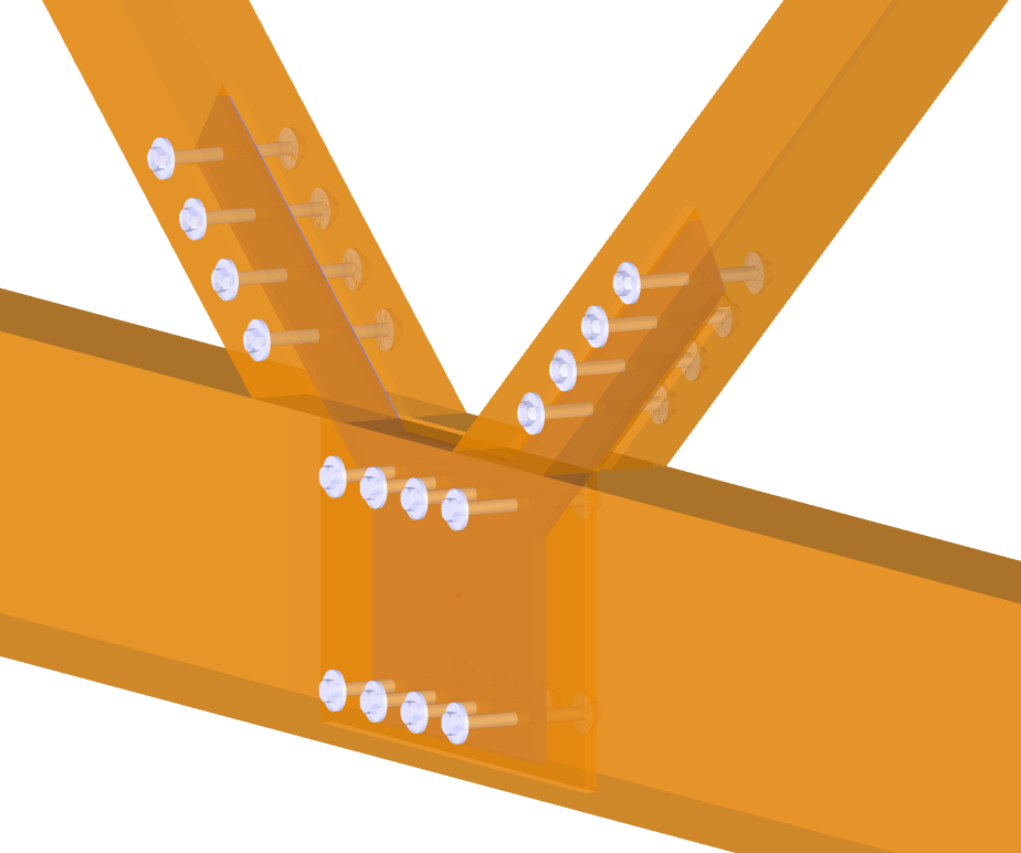
For non-standard connection design situations, the 3D modelling tools in RFEM can be used, see model image above. The connection is then designed using stress analysis and nonlinear material properties.
All connections are displayed as a 3D graphic with the output of all necessary dimensions of plates and members including bolt hole arrangements. The graphics can be transferred to the printout report including dimension lines as well as descriptions of bolts and welds, or sent to a DXF file output to place in a CAD drawing.
RFEM will also link to IDEA StatiCa, see below for more details.
Concrete Design
RFEM for the design of reinforced concrete beams and columns, flat slabs, walls, raft foundations planar structures according to Eurocode 2 for ultimate and serviceability limit state.
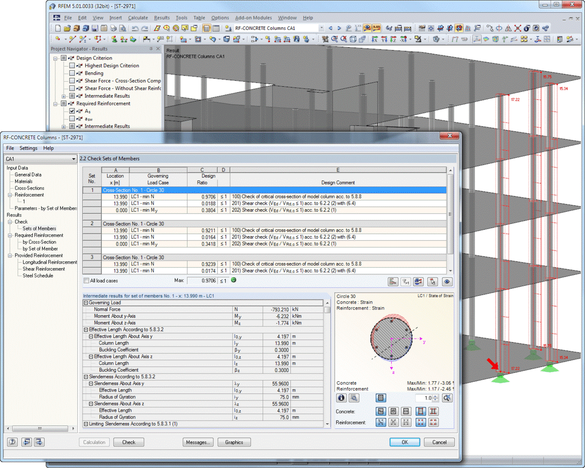
Concrete Design – Beams and Columns
For beams and columns, the program calculates the required longitudinal, shear and torsional reinforcement for all internal forces including biaxial bending and shear forces. It is also possible to design tapered and curved members.
The program will also allow for cracked sections considering tension stiffening as well as creep and shrinkage.
Output includes detailed explanations of any issues and results for all design locations allowing quick determination of any failure regions.
It is also possible to optimise cross-sections and visualise a concrete cross-section with rendered reinforcement in 3D and to produce an estimation of weight of materials.
Fire resistance design can also be performed according to the simplified method (zone method) according to EN 1992-1-2 for rectangular and circular cross-sections.
Graphical representation of results is presented on the model showing for example rendered beam and column reinforcement and required and provided reinforcement areas.
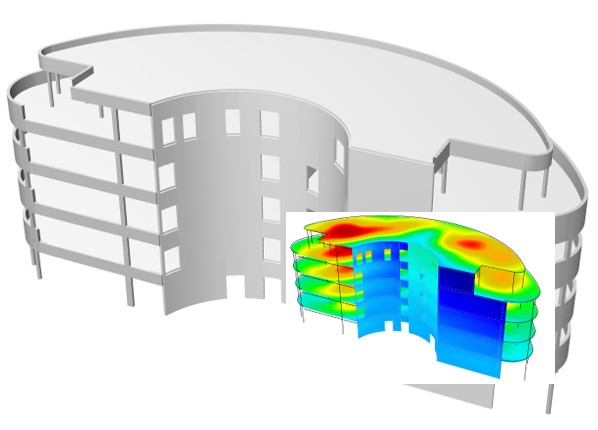
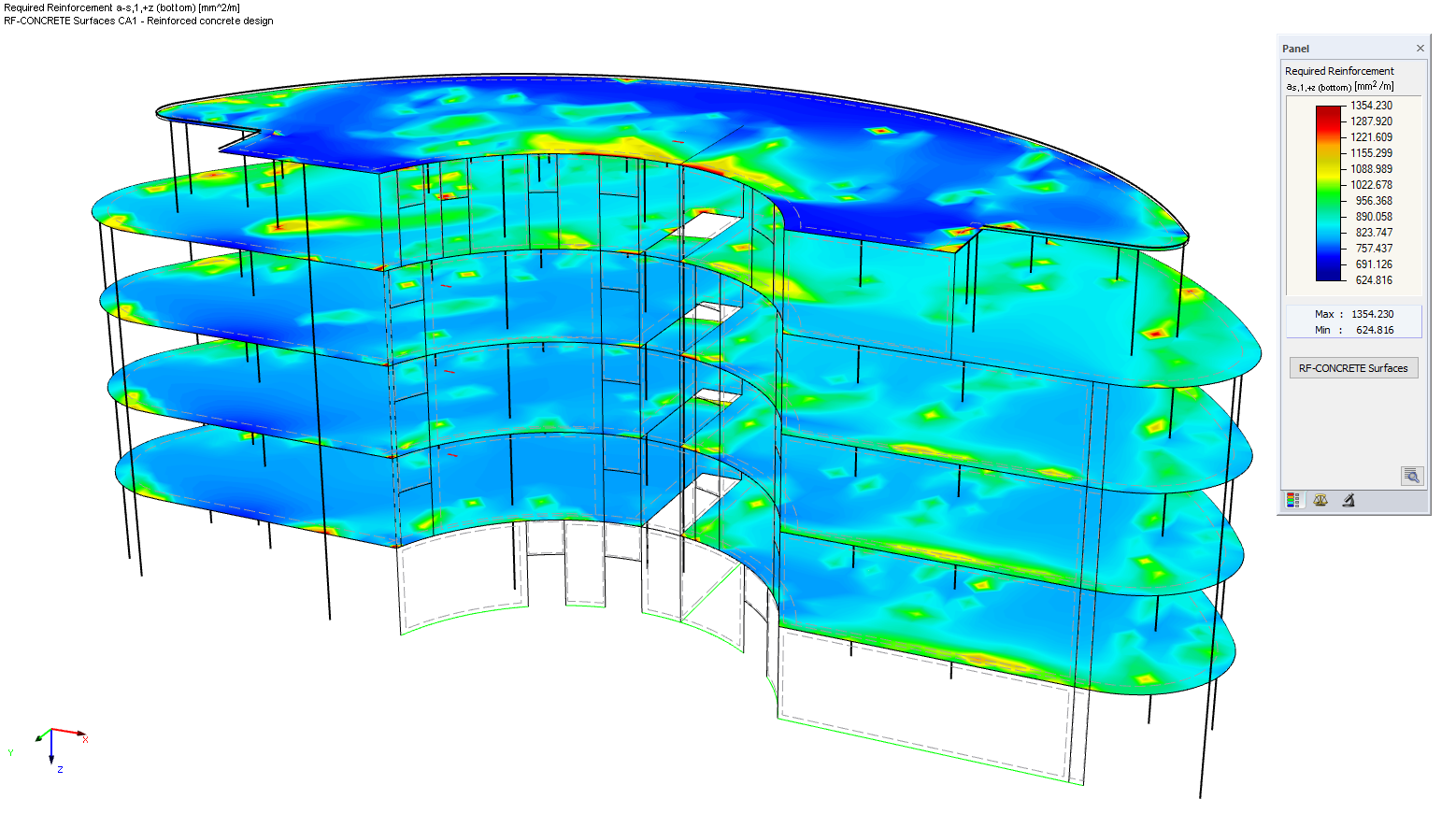
Concrete Design – Flat Slabs and Walls
Slabs can be designed with or without edge beams or ribs. If used, the beam reinforcement can be accounted for in the slab design to prevent the duplication of reinforcement in slab and beam members.
Theoretical reinforcement is calculated in the slab surfaces for either ULS, SLS or both in each orthogonal direction or in any user defined direction such as for skewed slabs or circular structures.
The results for required reinforcement can be smoothed with averaging tools over columns to prevent peak values, sections can be viewed through the slab for details at any stage.
Using the theoretically required reinforcement contours as a guide, the practical reinforcement, the intended in-situ reinforcement, can be input in each layer as a basic coverage with additional areas in regions where a need is shown.
Deflection checks of the slab can then be carried out that take account of practical reinforcement specified, this reinforcement can be subsequently edited to reduce deflections where required thus avoiding a need to increase in slab thicknesses.
To accurately calculate the deflections, the program runs a cracked section analysis to calculate the reduced stiffness of the slab. Tension stiffening between the cracks is included. Depending on the type of deflection required, immediate or long term, creep and shrinkage effects can also be included. The creep factor is either user input or automatically calculated from details of the concrete and type of cement.
Punching shear checks are automatically carried out at column locations, no need to input the nodes or even the locations such as corner, edge or central columns. Checks can also be made at wall corners and ends and for members attached to vertical walls.
Slab openings are automatically taken account of as defined in the RFEM model, additional openings, if required, can be manually added.
The check will determine where the concrete slab cannot withstand the shear force alone. In this case the additional punching shear reinforcement is specified for each failed node, or, the practical reinforcement can be used to increase the capacity of the node.
The load increment factor β is determined by full plastic shear distribution as constant factors according to the Eurocode or by user-defined specification.
Optional consideration of minimum moments can be included when determining longitudinal reinforcement.
Graphical representation of results is presented on the model showing for example required and practical/provided areas of slab reinforcement, contours and vectors of crack widths, creep deflections and punching shear checks.
Numerical results are also available in clearly arranged tables that interact with the user and the model to show any values selected.
Output of the slab reinforcement designed can be sent to CADS RC in AutoCAD or CADS RC3D for Revit, where the details can be converted to fully detailed drawings and schedules.
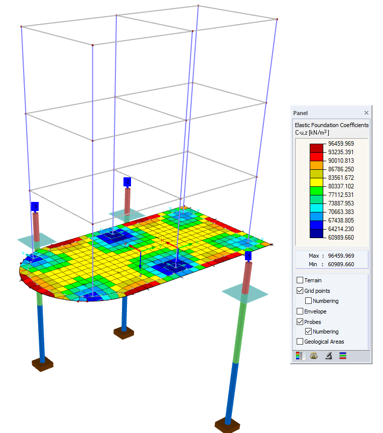
Concrete Design – Piled Raft Foundations
Raft foundations, with or without piles, can be simply modelled as a 2D slab with loads manually applied, or model the raft with the building on top as one 3D model.
Soil data can be entered as a 2D area support using soil subgrade values. These soil parameters, stiffness values, can be automatically calculated from a site borehole log using a soil structure interaction feature. The 3D soil stiffnesses are calculated from the site borehole logs which can be entered by plan location thus creating a true varying soil support.
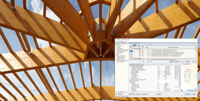
Timber Design – Members
RFEM designs timber members that can be circular, rectangular, or user-defined composite cross-sections (also hybrids), on the basis of the design procedures according to EN 1995. Members can be curved, tapered, or both, account is taken for the grain direction in design checks. There is an extensive material library in compliance with the Eurocode standards.
RFEM runs a stability analysis of members according to the equivalent member method or second-order analysis as well as designing to the serviceability limit state and for fire resistance. Furthermore there is the option to automatically carry out a cross-section optimization.
Output can be sent to Excel and includes a list of member lengths and weights. Details of the design results can be seen graphically on the structure in various configurable forms and colours.
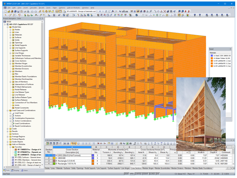
Timber Design – Cross-Laminated Timber Panels, CLT
A growing area in the use of timber seen with social housing and student accommodation is cross-laminated timber panels, (CLT).
RFEM performs a deflection analysis and stress design of laminate surfaces. The calculation allows the option of shear coupling using laminate theory. There are libraries of manufacturers built into the program, or, the CLT layer structure can be user input which can then be saved for future use.
The laminate layers are always an odd number in CLT panels, so a simple plate analysis is awkward due to varying stiffness in orthogonal directions. RFEM however will calculate these orthotropic properties based on the layer details thus saving time and guaranteeing accurate results.
Results include the maximum stresses, stress ratios, and displacements which can be displayed graphically on the model.
Timber Connection Design
The design of timber connections can be carried out where timber members are connected indirectly with steel plates or directly with slant screws.
The Steel to Timber Connection type designs joints where timber members are indirectly connected to each other by means of steel plates. Dowel-type fasteners are available: dowels, bolts, nails, and screws.
The Timber to Timber Connection type designs joints where timber members are directly connected to each other by means of slant screws.
Both the above connection types are designed according to EN 1995.
Glass Design
Analysis of the deformations and stresses of arbitrary shaped and curved glass surfaces.
It is possible to create all glazing types in the program, single layer glass, laminated and insulating glass with intermediate gas layer.
An extensive material library including all common types of glass, foil, and gas is available. The calculation is performed according to the following standards, DIN 18008:2010-12 and TRLV:2006-8.
Assignment of loads to load duration classes, the optional consideration of shear coupling of layers, and climatic loads.
Modelling and analysis of glass connections can be carried out, see supported canopy above.
Graphical representation of all results in RFEM with the ability to filter results and colour scales in result tables, direct data export to MS Excel.
Aluminium Design
The design of aluminium members for the ultimate and the serviceability limit state according to the standard EN 1999, (Eurocode 9).
Design to serviceability limit state for characteristic, frequent or quasi-permanent design situations.
A variety of cross-sections are provided, for example I-sections, C-sections, rectangular hollow sections, square sections, angles with equal and unequal legs, flat steel, round bars. All these sections can be automatically optimised.
User defined sections of complex extruded elements can be created from DXF data. Option also to manually input these graphically. The effective properties are then calculated.
There is also the capability to include the effects on the member strength of transverse welds.
All results are graphically displayed on the model, detailed results with references to the design equations used.
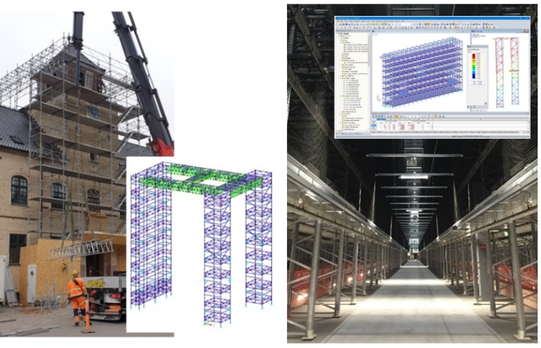
Scaffolding and Racking Systems
The design of scaffolding and racks considers various member and support connection nonlinearities such as yielding, tearing, slippage, etc. In addition, it is possible to define special scaffolding supports and member hinges in RFEM.
RFEM provides the nonlinearity option ‘scaffolding’ for the x and y rotational degrees of freedom of the nodal support, as required by the standards. After activating the option in the nodal support dialog box, an M-φ, (stiffness with rotation), diagram is shown for the supports selected.
The support remains moment-free, until the allowable slip rotation angle φ0 is reached. Then, the rotation does not change anymore until the moments described in the Mφ diagram are reached or until yielding occurs.
The member hinge nonlinearities enable the mechanical simulation of a joint between two tubes, standards, one inside the other, connecting the two members.
The model transfers the bending moment via the initially loaded outer tube and after positive locking additionally via the inner tube.
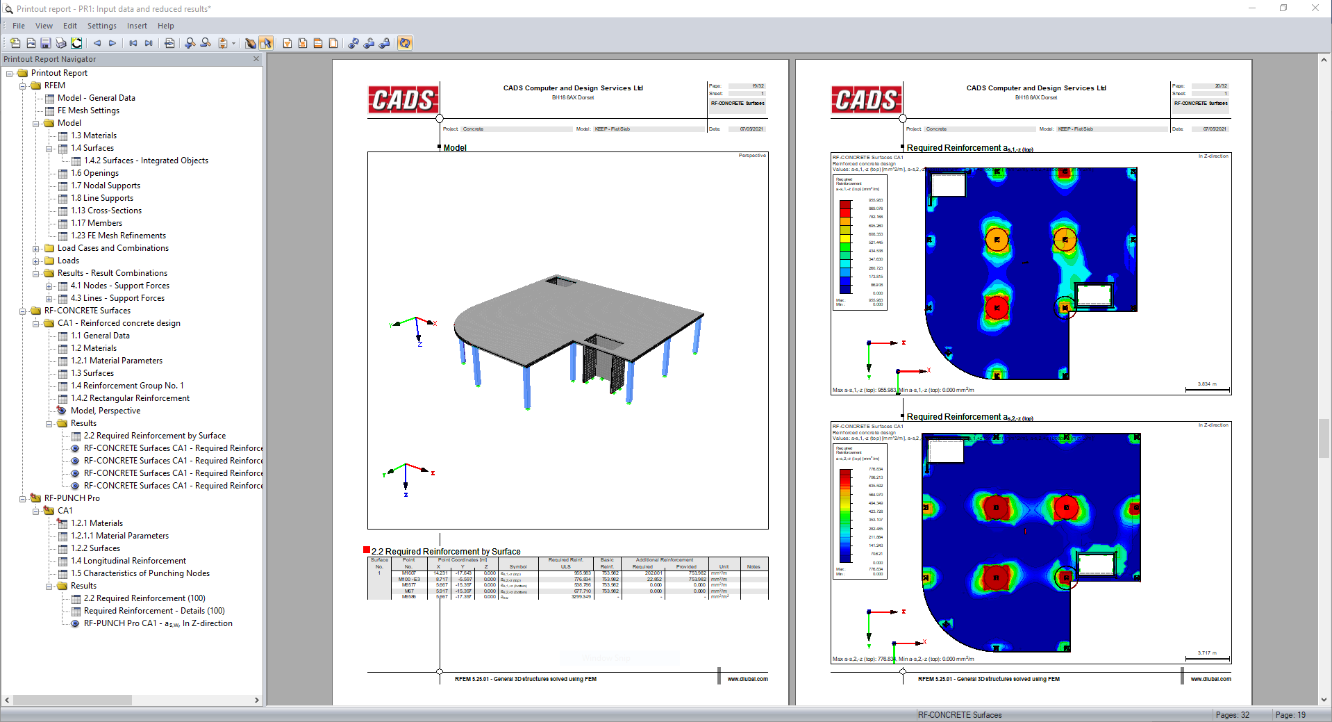
Calculation Document
The printout report, calculation document, is automatically generated from either a selection of suitable templates provided or you can develop your own user defined templates.
Within this report, images, text, and other elements can be added, they appear in a navigation column on the left of the screen.
Chapters and indents are automatically created but can be updated, items rearranged in location by “drag and drop” to alternate parts of the report, text changed.
Results can be filtered by node or member number, combination or results class and member section type. Keep results to a minimum, summarise, only report peak values of critical section types.
The report is dynamically linked to any changes to the project. Items that are changed such as loads, section sizes or design checks are automatically updated in the report tables and graphical images.
It is possible to create several printout reports for the model which is ideal if your structure is complex. Split the data into several small reports instead of creating one large report, the foundation and superstructure engineers may want different printout reports.
There are various language options available for the results: English, German, French, Spanish, Italian, Czech, Slovak, Hungarian, Polish, Dutch, Portuguese, Russian, and Chinese.
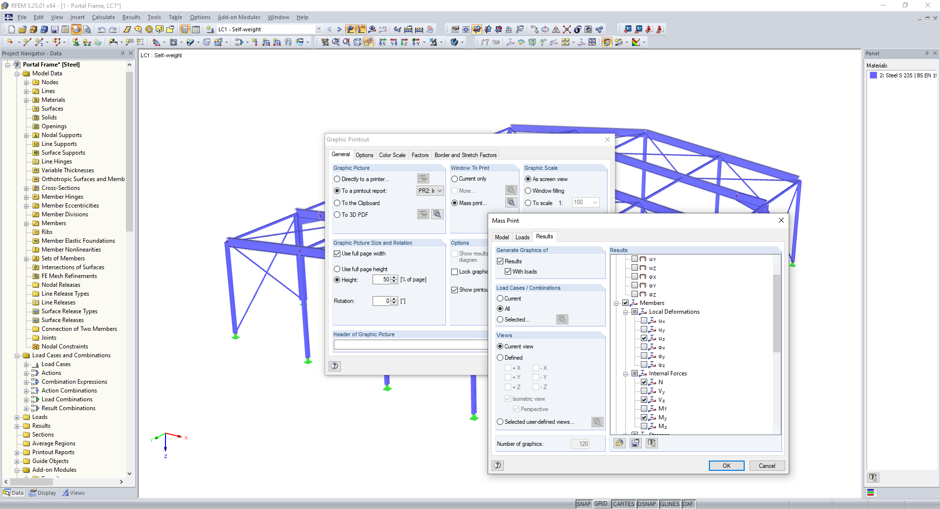
Mass Print of Graphics
It is possible to print an image of the model, all load types and results in one command. Images can be created with user defined orientations, height of page, title and render quality.
Print all internal forces as an isometric view, all design results in elevation, with a single mouse-click.
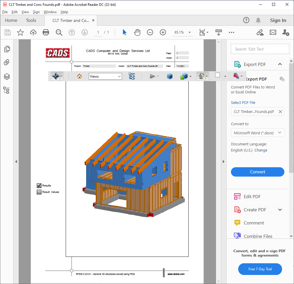
3D PDF Output
An option to create any image from the model including results as a 3D PDF image within the report. The recipient of the document, in Word or PDF formats, will be able to visualise the model or results by simply rotating the model with the mouse.

BIM
Dlubal Software programs all integrate seamlessly when conducting a Building Information Modelling (BIM) workflow.
A wide range of interface options ensures the opportunity of data exchange of digital building models with RFEM.
Direct interoperability with Revit, Tekla Structures and Bentley ISM. Other exchange formats are for Solidworks and Rhino and Grasshopper including DXF, IFC, STP and DSTV.
For full details of program interfaces, see the dedicated web page here.
View the technical information for Dlubal RFEM